If you have ever tried doing two things at once you will know how difficult it is unless you are an Arduino Portenta H7 with dual cores. This fun project showcases what is possible by adding an extra core into the mix when it comes to sensing colours and moving things around with motors and servos, all at the same time.
This robot colour sorter is capable of identifying and sorting random coloured counters (Skittles sweets) into containers of the same colour. It uses both cores of the Portenta, interacting using Remote Procedural Calls (RPC). One core controls a servo arm for moving counters from a loading tube to a colour sensor. The other core controls a stepper motor moving a carousel holding containers. This continuously rotates until a signal to the servo arm ejects the counter just at the right moment. Both cores run the processes concurrently in real-time.
1. Build the case
- Build a case from 3mm fibreboard. The dimensions are not critical, ours was approximately 200mm wide by 160mm deep and 110mm high.
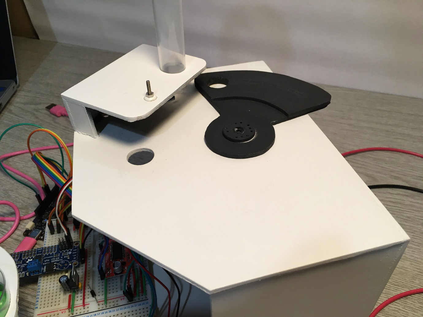
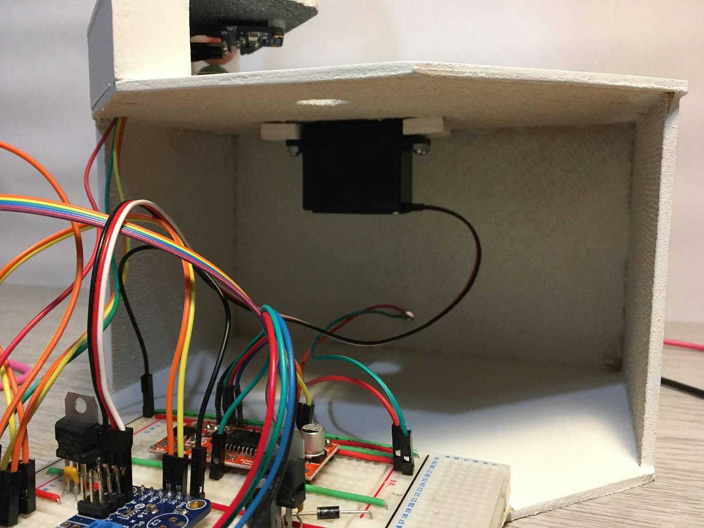
- A small 80mm by 60mm bracket holds the 18mm plastic feeder tube with a funnel for the counters. The colour sensor board is also mounted under this.
- A 90-degree servo arm is cut from double thickness 3mm fibreboard with a 15mm hole at one end to hold the counter. This moves in a 60mm radius arc from the centre of the servo. The loader tube, colour sensor and ejector hole must all align to this arc. The radial distance can be adjusted for in the servo control software. The arm is sprayed matt black to provide contrast to improve colour sensing.
2. Build the carousel
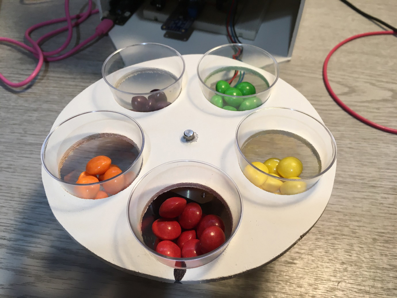 The carousel is cut from 3mm fibreboard and is 150mm in diameter. 5 off 40mm holes are cut to hold the plastic shot glass collector cups. These must be accurately spaced 72 degrees apart. A centre hole is drilled for the stepper spindle which is glued in place.
3. Build the stepper motor circuit
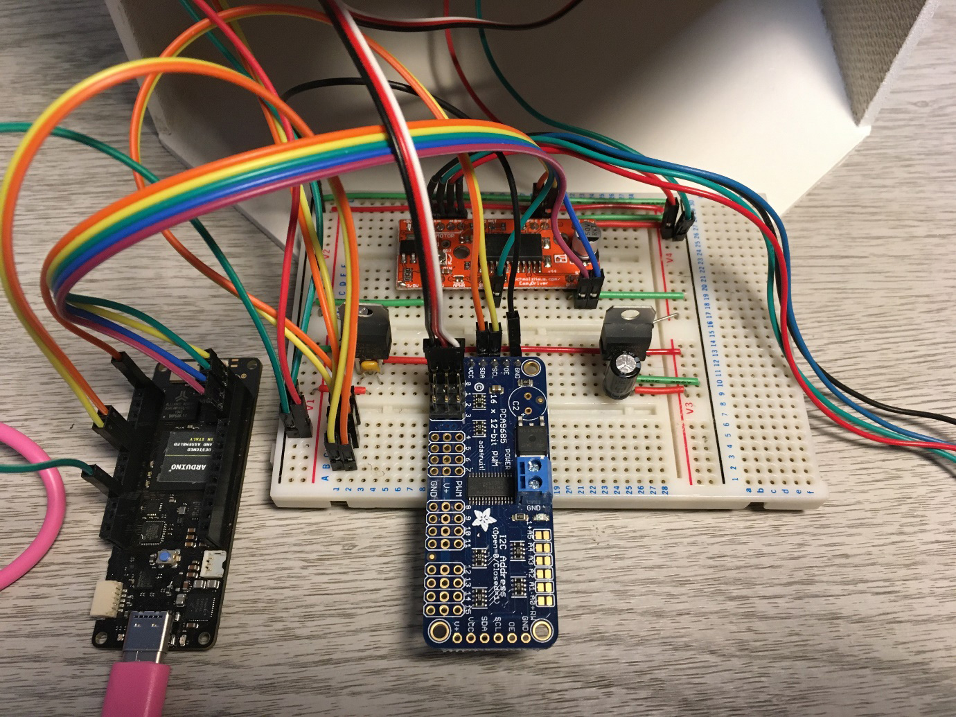
The complete circuit for the project can be built on a single large breadboard and it is built up in two parts.
- Start by completing the stepper motor circuit that rotates the carousel.
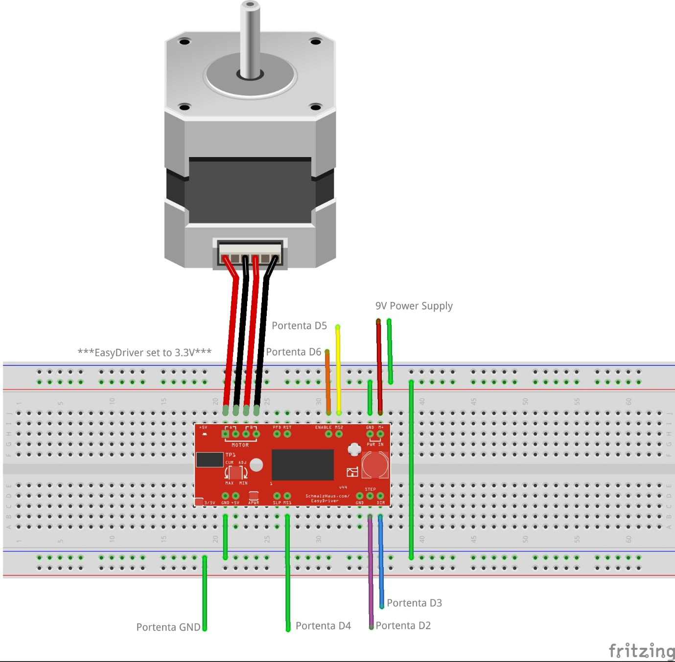
- To simplify controlling the stepper motor from the Portenta, an EasyDriver board is used, powered directly from a 9V power supply.
- The board has a small solder jumper in the bottom left-hand corner marked 3/5V – this must be bridged with solder so that the board operates at 3.3V making it safe to connect to the Portenta.
Connecting 5V to the Portenta I/O pins will permanently damage the board.
- Connect the stepper motor coil A & B wire pairs to the respective motor terminals on the EasyDriver.
Disconnecting the motor wires while powered on can damage the EasyDriver.
5 signal wires connect the Portenta digital pins to the EasyDriver plus a common ground:
- Step (STP) to Portenta D2
- Direction (DIR) to Portenta D3
- Micro-step 1 (MS1) to Portenta D4
- Micro-step 2 (MS2) to Portenta D5
- Enable (EN) to Portenta D
- GND to Portenta GND
4. Build the servo and colour sensor circuit
Controlling the servo safely and easily is done using an I2C servo driver board. The servo operates at 5V but the I2C signals must operate at 3.3V to make it safe to connect to the Portenta I2C pins.
- The servo is connected directly to the driver board.
- A 5V regulator connected to the 9V power supply creates a 5V rail on the breadboard to power the servo.
- A 3.3V regulator connected to the 9V power supply creates a 3.3V breadboard rail to power the servo driver board VCC and colour sensor.
Servo driver connections:
- V+ to 5V breadboard rail
- VCC to 3.3V breadboard rail
- SDA to Portenta SDA
- SCL to Portenta SCL
- GND to Portenta GND
A specialised I2C colour sensor board is used for sampling the colour of the counters. Again, this is connected so that VIN operates at 3.3V making it safe to connect to the Portenta I2C pins.
Colour sensor connections
- VIN to 3.3V Breadboard rail
- GND to Common GND
- SDA to Portenta SDA
- SCL to Portenta SCL
Ensure that the SDA / SCL lines are operating at 3.3V before connecting the Portenta. We used a multimeter to check this.
5. Install the software
Prepare your development environment by following the getting started guide for the Portenta H7 board.
6. Upload the M7 Core
Two independent Arduino applications run simultaneously, one on each of the Portenta H7 cores. The M7 core is responsible for controlling the servo driver and colour sensor signals. This controls the movement of counters from the loader to the colour sensor and then finally ejects them. Concurrently, the M4 core controls the stepper motor driver and indexes its position so that the counters are ejected at the right moment. The two processes are synchronised using Remote Procedural Calls (RPC).
After a counter colour has been identified by the sensor, the M7 core passes the colour index to the M4 core via RPC. When the carousel index for that colour matches, the M4 core executes an RPC on the M7 core which ejects the counter. In this way, both processes synchronise at the correct time.
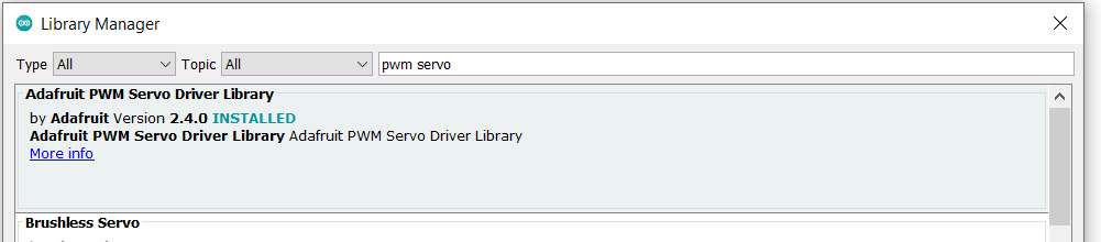
The servo and colour sensor use libraries provided by the board manufacturer which can be installed using the Arduino IDE Library Manager.
- Open the Library Manager and install the Adafruit PWM servo library.
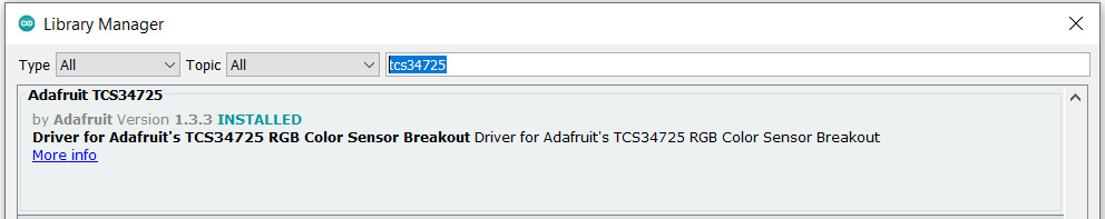
- Install the Adafruit TCS34725 colour sensor library.
The servo motor position can be adjusted by setting the following constants, so it stops in the correct place to load a counter, moves it to the sensor and then on to the ejector. They can be tuned during testing.
// Adjust position values accordingly
const int LOADER_POSITION = 168;
const int SENSOR_POSITION = 228;
const int EJECTOR_POSITION = 292;
Further information on controlling servos can be found here.
The sensitivity of the colour sensor can also be adjusted. It needs to be sensitive enough to distinguish between primary colours, so that different shades of the same colour are grouped together. If the sensitivity is set too high, we found it difficult to separate out the correct colours. Experimenting with the gain setting helps to widen the colour distance between two different colours. Red and green along with yellow and orange can be difficult to distinguish. Further parameter values can be found in the library header.
Adafruit_TCS34725 tcs =
Adafruit_TCS34725(TCS34725_INTEGRATIONTIME_2_4MS, TCS34725_GAIN_4X);
By experimentation, the colour matrix can be determined. Run samples of the same colour through when testing to adjust this. We found having a consistent light source above the sorter helped.
// Array of average RGB values
const int SAMPLES[][4] = {
  {23, 22, 19, WHITE},
  {16, 19, 12, GREEN},
  {11, 8, 8, VIOLET},
  {19, 10, 9, RED},
  {24, 16, 12, ORANGE},
  {35, 27, 17, YELLOW}
};
The RGB colour of each counter is compared against values in the matrix using a Euclidean colour distance strategy [https://en.wikipedia.org/wiki/Color_difference ] The sample with the lowest colour distance value is chosen.
float getColourDistance(int redSensor, int greenSensor, int blueSensor, int redSample, int greenSample, int blueSample)
{
return sqrt(pow(redSensor - redSample, 2) + pow(greenSensor - greenSample, 2) + pow(blueSensor - blueSample, 2));
}
After the sensor has taken a colour reading and the colour is identified, it is sent to the M4 core using RPC.
readSensor();
colours sample = identifySample();
if (sample == WHITE) {
eject = true;
}
  else {
colourIndex = (int)sample;
}
RPC1.call("setVar", colourIndex).as<int>();
The M7 waits in a loop until it receives eject signal from the M4:
while (!eject) delay(5);
After ejection, the ejector flag and colour index are reset, then sent to the M4 to signal for it to continue its rotation.
moveTo(EJECTOR_POSITION);
eject = 0;
colourIndex = 0;
delay(600);
RPC1.call("setVar", colourIndex).as<int>();
The full code listing for the M7 core can be found here on GitHub.
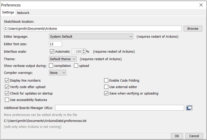
To compile RPC code, the -fexceptions flag needs setting. Create a file named platform.local.txt located at:
C:UsersusernameDocumentsArduinoDatapackagesarduino-betahardwarembed1.2.2
with the following contents:
compiler.cpp.extra_flags=-fexceptions
The root location for this on your system can be found by checking the setting at the bottom of the File -> Preferences dialogue
Next set the M7 core using the Tools -> Board item from the menu and upload the code.
7. Upload the M4 core
The M4 code runs the stepper motor controls, indexes the carousel and signals to the M7 core when it is time to eject. Each index position corresponds to one of the 5 counter colours. The index step is made up of smaller micro-steps. These are calculated for this particular stepper motor which has 200 full steps per complete revolution when set to run at eighth micro steps for the five different colours:
const int POSITIONS = 5;  // n platter positions
// Number of micro-steps to move one carousel position
const int MICROSTEPS = 200 * EIGTH / POSITIONS;
Further details about controlling stepper motors can be found here.
The main loop moves the carousel one index position at a time until the index matches the colour index set by the M7. At this point, the M4 sends the eject signal by RPC calling the ejector function on the M7.
void loop() {
  if (idx == colourIndex) {
    RPC1.call("setEjector", 1).as<int>();
    delay(DWELL);
  }
  moveOne(&idx, POSITIONS, MICROSTEPS, FORWARD);
}
The full code listing for the M4 core can be found here on GitHub.
Before uploading the code, set the M4 core in the Tools -> Board menu:
8. Testing and running
For this build, we left the Portenta powered using the USB cable. This allows access the serial output making adjustments to the servo and colour parameters easier.
It is not straight forwards to debug code running on the M4 core. This is where the new Arduino Pro IDE would help but we found the Alpha version this to be unstable at the time. During code development we did notice that if there was contention when making RPC calls, the on-board LED began flashing red indicating a fault.
To run the system, set the carousel with one cup beneath the ejector, hold the Portenta reset and turn the power on. When the Portenta resets, the carousel will start running continuously whist the loader initialises and starts trying to load a counter.
After adding counters, once the first one has its colour identified, the carousel will pause when it reaches the correct index for that colour. When the counter supply runs out, the carousel will return back to running continuously again until more counters are added.
Summary
Having two cores to deal with can add a level of difficulty to a project but once you get used to it, it can make complicated projects simpler and easier to build and test. With robots, it allows sensing to be carried out in parallel to motor control, which can be essential in autonomous, reactive systems.
Although it would be possible to build this project using a single core microcontroller, every operation would have to be sequential. Because the Portenta H7 has dual cores it makes doing two things at one possible.
If you get a skittle that will not scan correctly just eat it! Have fun.
Like what you read? Why not show your appreciation by giving some love.
From a quick tap to smashing that love button and show how much you enjoyed this project.

