If your project involves controlling motors to give precise movement, when a gear set needs to rotate a given number of turns, or a turntable needs rotating so many degrees, then a stepper motor might be the right choice.
This project demonstrates how to control the EasyDriver board using Python and the GPIO library built into Raspbian.
1. Get your Pi ready
- You should start with a WiFi-enabled Raspberry Pi connected to mouse, keyboard and monitor, you can learn here how to do it using an Okdo Pi kit.
2. Prepare the EasyDriver
EasyDriver is an open-source, stepper motor driver with several convenient features that make driving stepper motors from the Pi 4 GPIO safe and effective. It operates between 6V and 30V at a maximum current rating of 750mA/phase. It can drive 4, 6 and 8 wire stepper motors in full, half, quarter or eighth step modes according to the settings of MS1 and MS2 pins. Pin DIR sets the direction and pin SLP puts the board into sleep mode. It also has an auxiliary output that can source up to 50mA at its operating voltage.


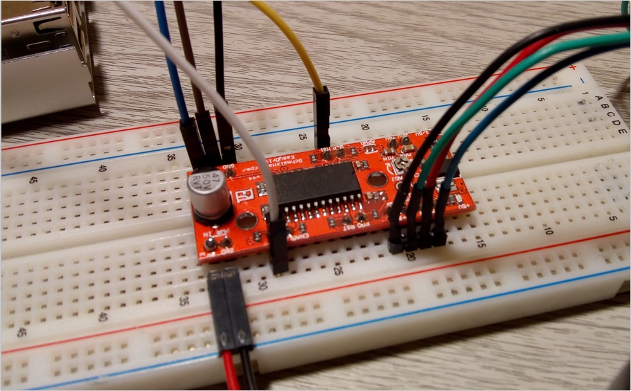
The board operates at 5V by default, which would damage the Pi 4 GPIO outputs. Change this to 3.3V by bridging with solder the pads in the bottom left corner of the board marked 3 /5V.
Use a multi-meter to check the operating voltage of GPIO inputs/outputs before connecting the Pi. Measure the voltage across the GND / STEP connections. This should read 3.3V
The EasyDriver requires a separate DC power supply of between 6V to 30V – a 9V DC / 2A power adapter is suitable for this project.
3.Prepare the motor
The motor used in this project is a 4 wire type with 200 steps per revolution. In full-step mode it can be positioned accurately at 1.8° increments. In eighth step mode, it can be positioned at 0.225° increments.
4 wire stepper motors have 2 pairs of connected coils. These should be soldered to adjacent pins on a four-pin male header to provide a secure connection. Insulate the connections with heat-shrink tube. The datasheet for your motor should have the connections listed as there is no common standard.
For the example motor the connections are:
Pin 1: Blue
Pin 2: Red
Pin 3: Green
Pin 4: Black
Never disconnect the motor from the EasyDriver while the board is powered on, as this will permanently damage the EasyDriver
4. Build the circuit
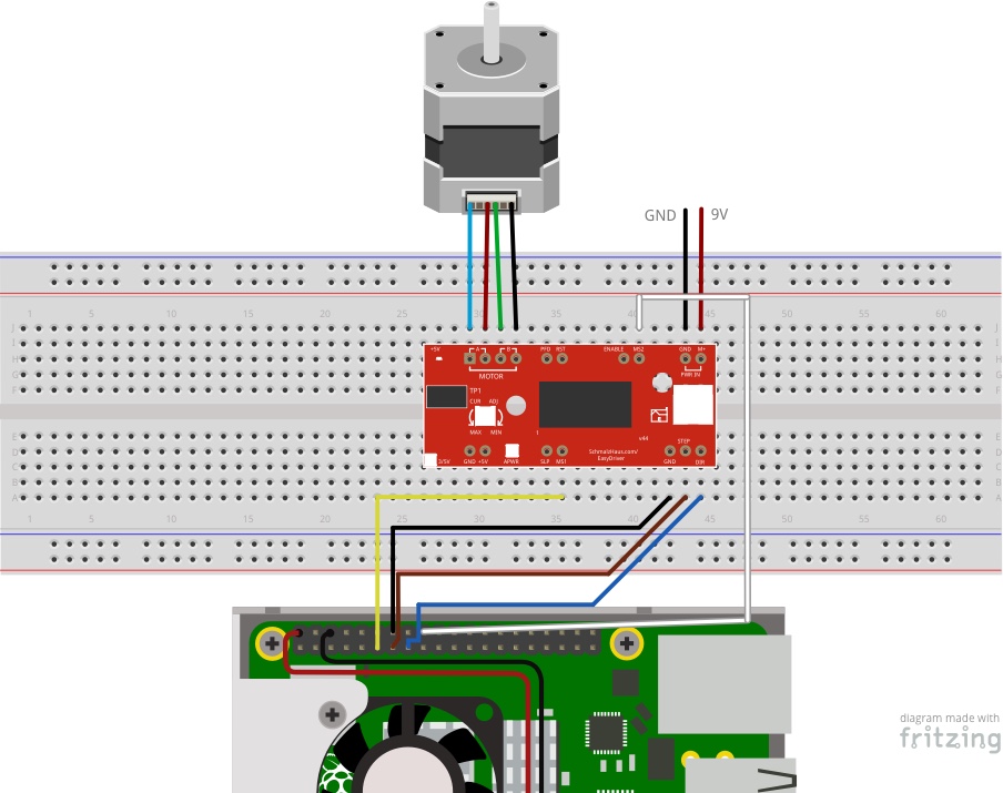
Pi 4 to EasyDriver connections:
- Connect a female-male jumper from GPIO pin 17 to EasyDriver MS1 (Yellow)
- Connect a female-male jumper from GPIO pin 27 to EasyDriver STEP (Brown)
- Connect a female-male jumper from GND to EasyDriver GND (Black)
- Connect a female-male jumper from GPIO pin 22 to EasyDriver DIR (Blue)
- Connect a female-male jumper from GPIO pin 24 to EasyDriver MS2 (White)
Motor to EasyDriver connections:
- Connect Motor pin 1 to EasyDriver A1 (Blue)
- Connect Motor pin 2 to EasyDriver A2 (Red)
- Connect Motor pin3 to EasyDriver B1 (Green)
- Connect Motor pin 4 to EasyDriver B2 (Black)
Power supply to EasyDriver connections:
- Connect power supply GND to EasyDriver GND (Black)
- Connect power supply 9V to EasyDriver M+ (Red)
Double-check the connections before applying power to the motor to avoid damaging the Pi 4 or motor driver.
5. Control with Python
The EasyDriver inputs can be controlled using the GPIO Python library which is included with the default desktop version of Raspbian.
- Open the Geany IDE from the Main Menu > Programming > Geany and copy and paste the code below into a new tab. The example code drives the motor first clockwise in eighth step mode, 90 degrees at a time. It then reverses direction and rotates back to the origin in full-step mode.
- While the test program is running adjust the small pot on the EasyDriver until the motor turns smoothly.
import RPi.GPIO as GPIO
import time

# GPIO pin numbering
step_pin = 27
dir_pin = 22
ms1_pin = 17
ms2_pin = 24

delay = 0.001  # 1 microsecond
GPIO.setmode(GPIO.BCM)
GPIO.setup(dir_pin, GPIO.OUT)
GPIO.setup(ms1_pin, GPIO.OUT)
GPIO.setup(ms2_pin, GPIO.OUT)
GPIO.setup(step_pin, GPIO.OUT)

def steps(n):
    count = 0
    while count < n:
        GPIO.output(step_pin, GPIO.HIGH)
        time.sleep(delay)
        GPIO.output(step_pin, GPIO.LOW)
        time.sleep(delay)
        count += 1

try:
    while True:
        # Rotate clockwise in eighth step mode
        GPIO.output(dir_pin, GPIO.HIGH)
        GPIO.output(ms1_pin, GPIO.HIGH)
        GPIO.output(ms2_pin, GPIO.HIGH)
        for i in range(4):
            steps(200 * 8 / 4)  # Rotate 90 degrees
            time.sleep(1)
        # Rotate anti-clockwise in full step mode
        GPIO.output(dir_pin, GPIO.LOW)
        GPIO.output(ms1_pin, GPIO.LOW)
        GPIO.output(ms2_pin, GPIO.LOW)
        for i in range(4):
            steps(200 / 4)  # Rotate 90 degrees
            time.sleep(1)
except KeyboardInterrupt:  # Exit on CTRL+C
        GPIO.cleanup()  # Cleanup GPIO
The program imports the GPIO and time modules and sets up the GPIO pins according to the Broadcom pin numbering scheme, not the physical header pin numbers and sets them as outputs.
A function called steps is defined which moves the motor the given number of steps according to the value of parameter n. It does this by pulsing the STEP pin HIGH and then LOW for each step.
The step mode and direction are then set. This can be full, half, quarter and eighth step according to the following table:
| MS1 | MS2 | Mode |
| Low | Low | Full step |
| High | Low | Half step |
| Low | High | Quarter step |
| High | High | Eighth step |
To rotate this motor 90 degrees in Full step mode takes 200 / 4 steps. The while loop rotates the motor in 90 degree increments until Ctrl + C is pressed.
Power on the motor and execute the code from the Build menu to run the example.
6. Do more
The stepper motors speed of rotation is controlled by the step mode. Change the step mode by altering the MS1 / MS2 levels according to the table above. Full step will move the motor fastest, eighth mode the slowest.
Change motor direction by setting the DIR pin High or Low.
Add another GPIO connection to the SLP pin to put the motor into sleep mode, saving power when the motor has finished moving. Wake it up when it needs to move again.
Use an electromechanical limit switch to position the motor at a datum point then move the motor, counting each step relative to that point. This allows for very accurate control.
Summary
This project has shown how stepper motors can be controlled using the Pi 4 and a dedicated EasyDriver stepper motor board.
Stepper motors are used in applications like 3D printers, CNC machines and Robotics where precise positioning is involved. They can also be used when a holding torque is required while the motor is stationary.
The Pi 4 can control the speed, number of steps and direction of the motor using Python and the GPIO library built into Raspbian, to provide precise positioning of the motor for your application.
Like what you read? Why not show your appreciation by giving some love.
From a quick tap to smashing that love button and show how much you enjoyed this project.

