Many robotics and automation projects require controlling one or more DC motors using the Pi4. This project demonstrates how to easily and safely control DC motors using an L293D Motor Driver IC circuit that can control either one or two DC motors between 4.5V and 36V at continuous currents of up to 600mA per motor.
1. Get your Pi ready
- You should start with a WiFi-enabled Raspberry Pi connected to mouse, keyboard and monitor, you can learn here how to do it using an Okdo Pi kit.
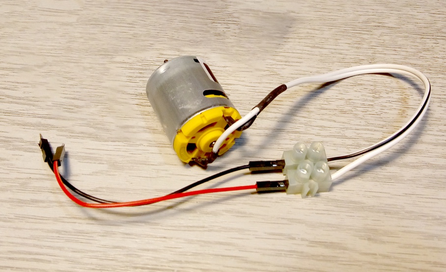
2. Prepare the motor
The DC motor used in this project operates between 6V and 15V DC. Typically, the motor sinks about 130mA at 12V which is well within the limits of the L293D driver.
Slide heat shrink tubing over two lengths of hook-up wire, then solder to the motor terminals and shrink over the connection. Connect the wires to a screw terminal block. Then attach black and red male to male jumper wires from the terminal block.
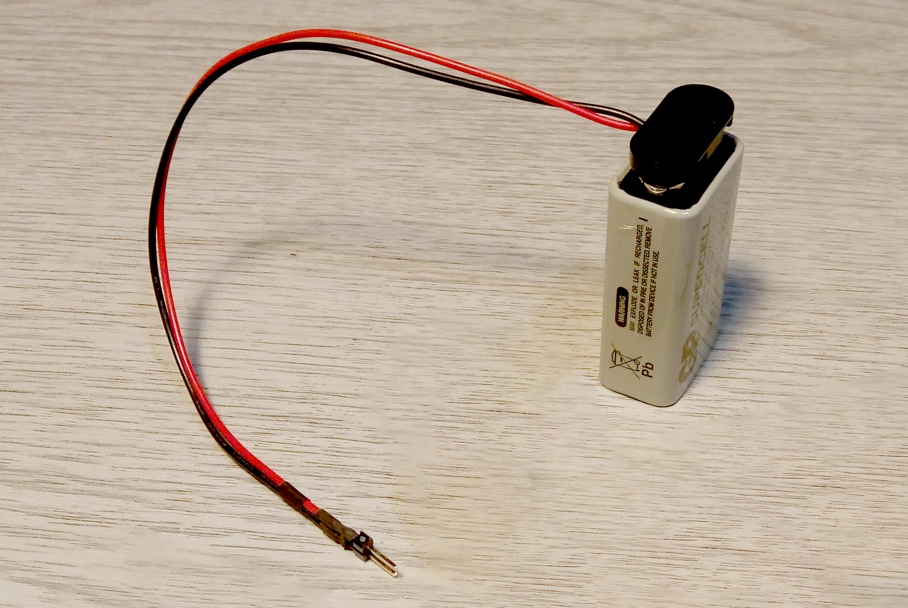
3. Prepare the battery
The power to test the motor will come from a 9V battery although any DC power supply up to a maximum of 15V is suitable.
- Cut two lengths of heat shrink tubing and place over the battery connector wires, then solder the wires to a 2 pin male header and shrink the tubing.
- Attach the connector to the battery.
4. Build the citcuit
Make sure that the Pi is powered off and the battery is disconnected before building or changing the circuit.
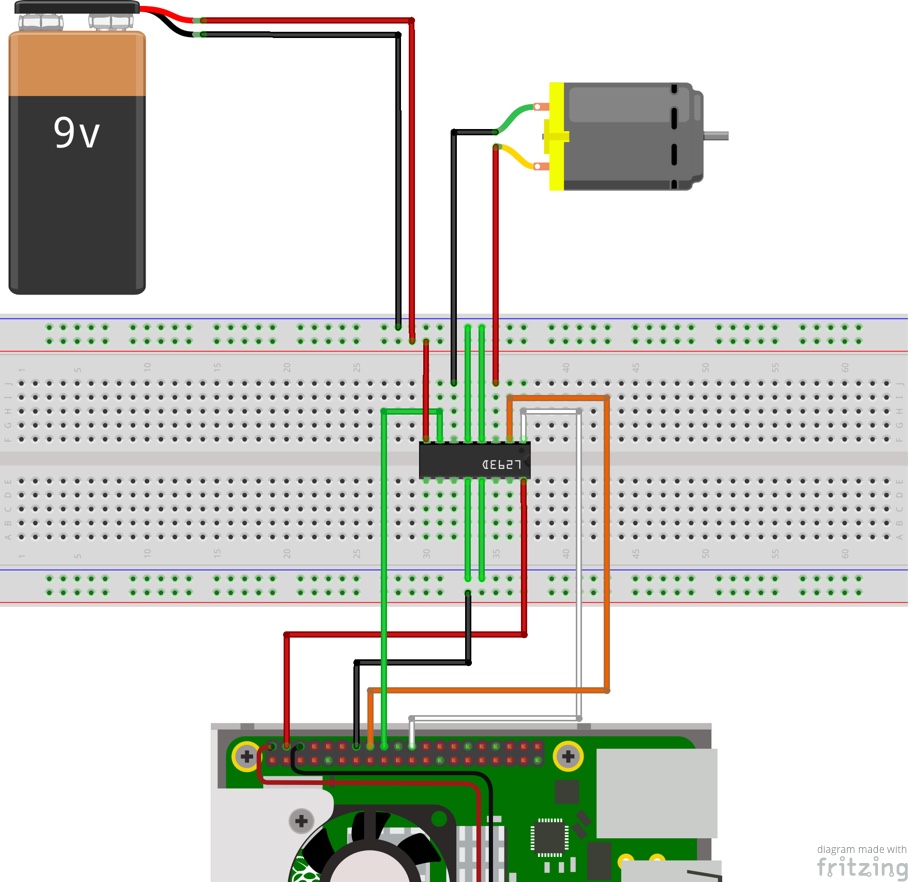
- Insert the L293D IC across the centre of the breadboard noting the orientation of the notched end of the IC.
L293D Breadboard connections:
- Connect jumper wires from L293D pins 4, 5, 12 and 13 to the GND rail on either side of the breadboard.
- Connect a jumper wire from L293D pin 8 to the 9V positive rail of the breadboard.
Pi to L293D connections:
- Connect a female-male jumper from GPIO pin 25 to L293D pin 1 (white)
- Connect a female-male jumper from GPIO pin 23 to L293D pin 2 (orange)
- Connect a female-male jumper from GPIO pin 24 to L293D pin 7 (green)
- Connect a female-male jumper from GPIO 5V to L293D pin 16 (red)
- Connect a female-male jumper from GPIO GND to breadboard GND rail (black)
- Connect a male-male jumper across both GND rails on the breadboard.
Motor to L293D connections (either way round):
- Connect Motor terminal 1 to L293D pin 3 (red)
- Connect Motor terminal 2 to L293D pin 6 (black)
Double-check the orientation of the notch on the L293D and the connections before applying power to the motor, to avoid damaging the Pi or motor driver.
Battery to Breadboard connections:
- Connect battery GND to the breadboard GND rail (black)
- Connect battery 9V to the breadboard 9V rail (red)
- Connect the 100uF electrolytic capacitor across the 9V and GND rail near to the battery connection. The negative lead of the capacitor must be connected to the GND rail.
Always make sure the negative side of the battery is connected to the GND (Blue) rail and the 9V side of the battery is connected to the 9V (Red) rail of the breadboard.
5. Control with Python
The L293D inputs can be controlled using the GPIO Python library. This is included with the default desktop version of Raspbian.
Open the Geany IDE from Main Menu > Programming > Geany and copy and paste the code below into a new tab.
The example code drives the motor first forwards, ramping up the power to the motor incrementally. Then it stops the motor and reverses its direction before ramping up the power again and stopping.
import RPi.GPIO as GPIO
import time
GPIO.setmode(GPIO.BCM)
Motor1A= 23
Motor2A = 24
Motor1EN = 25

GPIO.setup(Motor1A, GPIO.OUT)
GPIO.setup(Motor2A, GPIO.OUT)
GPIO.setup(Motor1EN, GPIO.OUT)

def forward():
    GPIO.output(Motor1A, GPIO.HIGH)
    GPIO.output(Motor2A, GPIO.LOW)

def reverse():
    GPIO.output(Motor1A, GPIO.LOW)
    GPIO.output(Motor2A, GPIO.HIGH)

def ramp_up():
    pwm.start(80)
    for i in range(80, 110, 10):
        pwm.ChangeDutyCycle(i)
        print("{0}%".format(i))
        time.sleep(5)

pwm = GPIO.PWM(Motor1EN, 1000)
forward()
ramp_up()
pwm.stop()
time.sleep(1)
reverse()
ramp_up()
pwm.stop()

GPIO.cleanup()
The program imports the GPIO and time modules and sets up the GPIO pins according to the Broadcom pin numbering scheme, not the physical header pin numbers. All the pins are set as outputs.
Functions forward() and reverse() are defined which configure one pair of motor inputs to control the direction of the motor according the table below:
| 1A | High | Low |
| 2A | Low | High |
| Direction | Forward | Reverse |
A function named ramp_up() configures a PWM output from the Pi4 to control the speed of the motor using the L293D Enable pin. The motor runs at full speed when the PWM output is set to 100% duty cycle. Reducing the duty cycle percentage reduces the speed of the motor.
The code then sets up the Enable pin as a PWM output, sets the direction of the motor, then ramps up the speed of the motor until full speed is reached, before reversing the direction and stopping the motor.
Finally the GPIO pins are reset in the cleanup() function call.
To run the demonstration code, attach the battery and execute the code from the Build menu. The motor should run the test cycle then stop and the program will exit.
6. Do more
Motor direction is set by driving the motor input logic pins and speed is set by driving the voltage level of the Enable pin using a PWM output from the Pi.
There are 2 pairs of motor inputs, one for each motor and an enable pin so these can be set individually to drive 2 motors independently or together.
Add a second motor by connecting the opposite bank of the L293D and 3 additional GPIO pins to drive the motor input and enable pins.
Connect the motor to a fan and add a digital thermometer that acts as an input to the Pi. Map the temperature to the PWM duty cycle to adjust the fan speed at different temperatures to create a custom fan controller.
Summary
DC motors are used in applications like robotics, electric vehicles and to drive motor gear boxes and fans, where stop / start and continuous motion is involved. They are used when continuous control of both speed and direction of rotation are required.
This project has shown how DC motors can be controlled using the Pi and a L293D motor driver IC. The L293D has built in clamping diodes to simplify and reduce the number of components in the driver circuit.
Using a single L293D it is possible to control one or two DC motors with voltage ratings of up to 36V and 600mA of continuous current per channel.
The Pi 4 can control the motor speed and direction using Python and the GPIO library built into Raspbian, to provide safe and flexible motor control for your project.
Like what you read? Why not show your appreciation by giving some love.
From a quick tap to smashing that love button and show how much you enjoyed this project.

