This project features the Arduino Portenta Machine Control board – a fully-centralized, low-power industrial control unit that is ideal for AI and industrial automation applications. Following this step-by-step guide, you’ll discover how to use this Arduino board to control industrial appliances using remote sensors and MQTT.
The Portenta Machine Control (PMC) is an addition to the Arduino Pro range of products based around the Portenta H7, 32bit, STM32H747XI dual Cortex®-M7+M4 low power Arm® MCU. Rated at 24V, it has a plethora of industrial spec I/O and communications protocols, including Ethernet, WiFi / BLE wireless, CAN Bus, RS232, RS422, RS485 and a Real-Time Clock. It has 16MB of flash memory and 8MB of SDRAM.
The PMC is actually an expansion board for the included Portenta H7 module that is mounted on the back of the board. The USB to Serial programming connector and SMA antenna connector are brought out to the front of the board, and the PCB comes in an enclosure suitable for DIN rail mounting measuring 170mm x 90mm x 50mm high.
Arduino also offers a dual-licensing program for Arduino Pro based products.
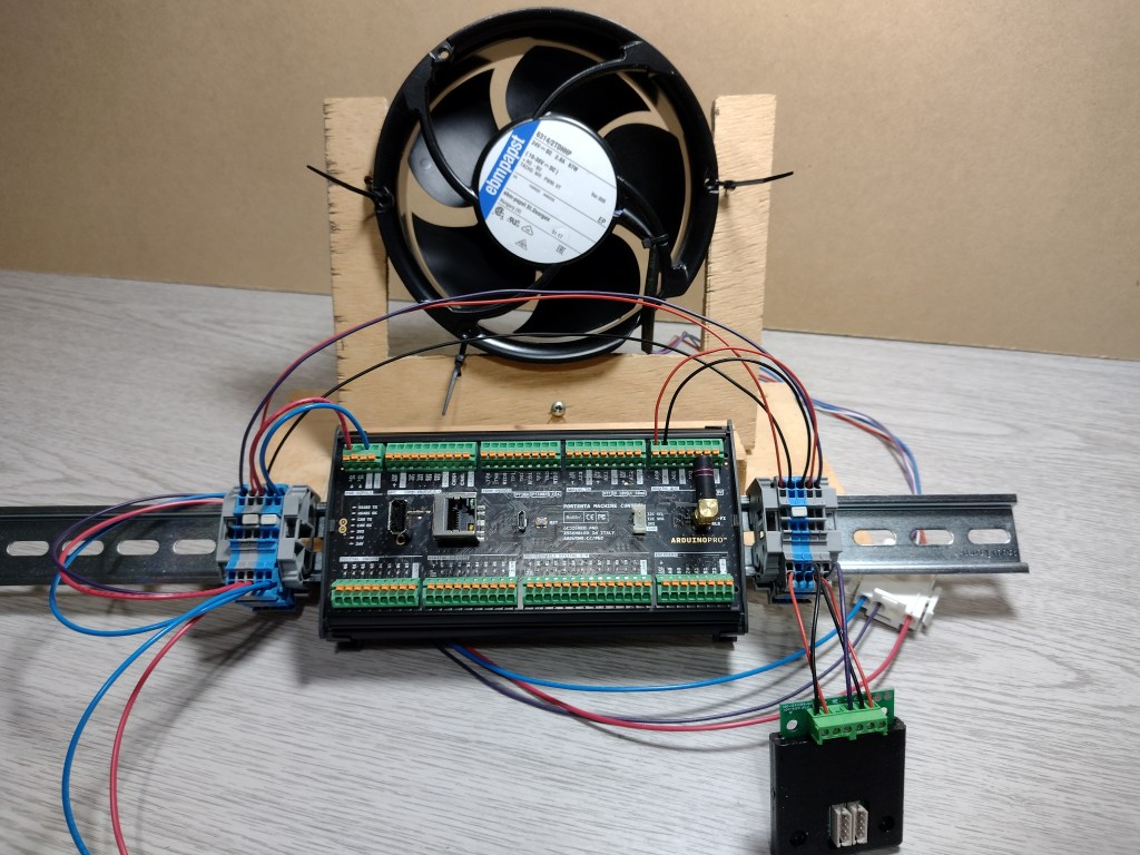
In this project, we use the PMC to connect to remote CO2 sensors via MQTT over WiFi to control a 24VDC industrial fan. The prototype was built using standard, off the shelf industrial DIN connectors.
Developing the firmware in C/C++ using the latest Arduino IDE 2.0 gives access to a large number of existing Open Source libraries. We used the PMC’s onboard WiFi to connect to a remote MQTT server on the LAN that publishes local environmental data in JSON format. The PMC firmware handles the WiFi connection, and MQTT client and extracts CO2 readings from the message payload. CO2 levels are mapped to one of the analogue output channels of the PMC connected to an industrial Fan Controller, which drives a PWM signal input for the Fan itself.
The project Firmware is available for download from the OKdo GitHub repo
(Copyright © 2014-2022, Benoit BLANCHON).
Step 1: Circuit
The circuit is built from industrial spec components mounted on standard 32mm DIN rail. The PMC comes in a DIN rail housing, but it also has 4 mounting holes in the PCB if you want to mount it directly via stand-offs. The Fan Controller and Fan are coupled using Wago 2000 push-fit DIN rail terminal blocks and 18 AWG hookup wire for power and 22 AWG for signals.
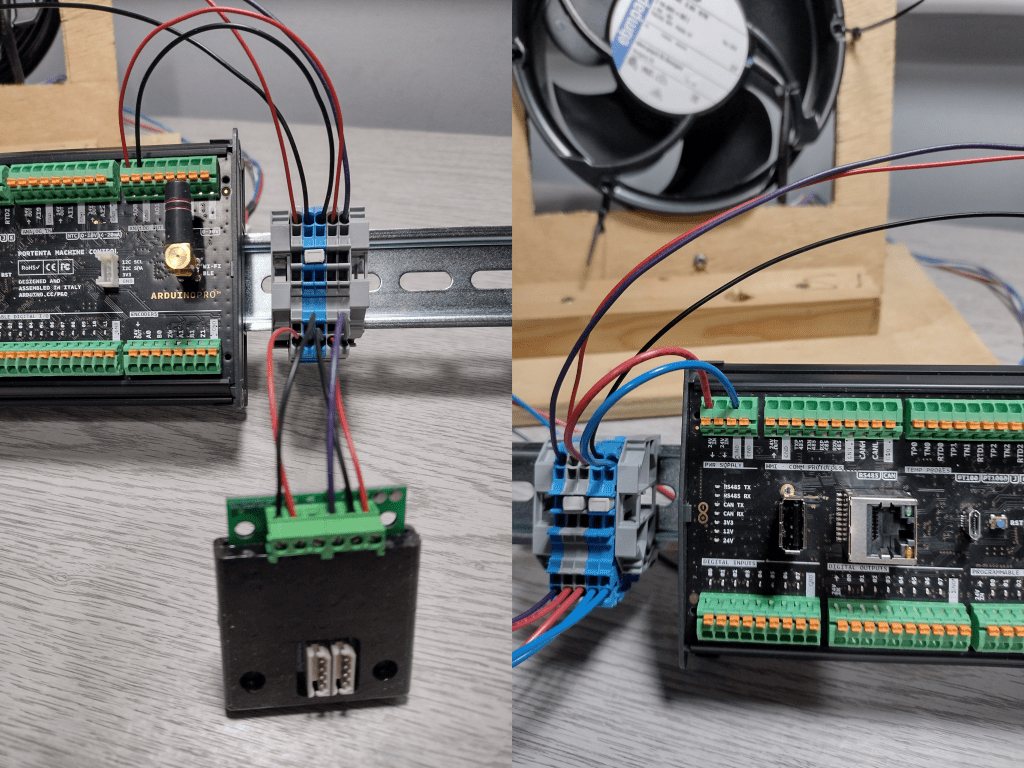
All the PMC terminal blocks are push-fit types capable of securely connecting cable sizes up to 18 AWG.
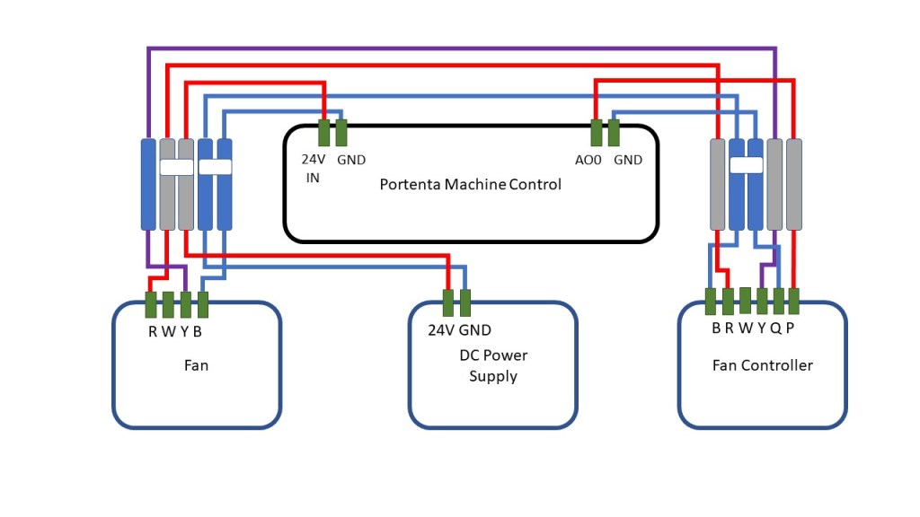
The PMC unit is powered from the 24V DC rail with the 0 – 10V Analogue Output Channel connected to the Fan Controller’s analogue input. All grounds are connected to the common GND rail. We used a 24VDC / 90W bench power supply for testing purposes.
Portenta Machine Control connections:
| Terminal | Portenta Machine Control |
| 24V IN | 24V DC input |
| GND | GND |
| AO0 | 0 – 10V Analogue output |
| GND | GND |
The EBM Papst CGC Fan Control unit is powered from the 24V rail and takes a 0 – 10V control signal from the PMC Analogue Output channel. All grounds are connected to the common GND rail.
Fan Controller connections:
| Terminal | Fan Controller |
| P | 0-10V control signal input |
| Q | GND (0V) control signal input |
| Y | Open Collector PWM output |
| W | Open collector tacho input (NC) |
| R | 24V DC supply |
| B | GND (0V) |
The EBM Papst Fan, rated at 67W, connects directly to the 24V rail and common GND. It takes an Open Collector PWM control signal from the Fan Controller. There is also an Open Collector PWM tacho output that can be used to sense the fan speed, but we left this unconnected.
Fan Connections:
| Terminal | Fan |
| R | 24V DC |
| W | Open collector tacho output |
| Y | PWM control signal input |
| B | GND |
Step 2: Programming Environment
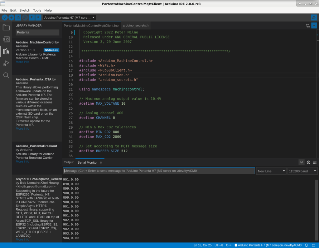
The Arduino IDE 2.0 version environment was downloaded and installed on a PC running Debian Linux, but it is also available for Windows and Mac OS. The PMC is compatible with the other Arduino environments and 3rd party ARM IDE’s.
To get the IDE to run, we had to change ownership to root and enable the setuid bit on the chrome-sandbox sub-directory of the Arduino-ide installation:
cd ~/arduino-ide_2.0.0-rc3_Linux_64bit
sudo chown root:root chrome-sandbox
sudo chmod 4755 chrome-sandbox
Arduino provides a custom library for the PMC – Arduino_MachineControl, which can be installed from the library manager or GitHub download.
There are several MQTT clients available which will run on the Portenta, including Arduino’s ArduinoMqttClient, but we had issues re-starting a connection if the client disconnected for some reason. In the end, the PubSubClient library proved reliable, so we used that for our MQTT client.
The same goes for JSON parsers. There are several to choose from, including Arduino_JSON, which is in Beta and doesn’t run for long periods without issues. We found the ArduinoJSON library to be very reliable and excellently documented.
Step 3: WiFi
The attached Portenta H7 module has a Murata 1DX dual WiFi and Bluetooth 5.1 onboard wireless module with the antenna connection brought out to an SMA connector on the front of the PCM board. You need to add a 2.4GHz SMA antenna as this does not come with the product.
The following standard code used in the main loop gave a reliable network connection which would reconnect if there were any network connectivity issues:
 if (WiFi.status() != WL_CONNECTED) {
    // Wifi.begin blocks until connect or failure timeout
    WiFi.begin(ssid, pass);
    delay(10000);
  }
Tip: We needed to use a hardcoded IP address for servers on our LAN, but hostnames worked for external addresses.
Step 4: MQTT
Maintaining a reliable MQTT connection proved to be the most difficult part of the project. We started by trying Arduino’s own MQTT client library but couldn’t get it to reconnect if the connection timed out and was disconnected.
After several attempts, we switched to the more mature PubSubClient library, which also had reconnection issues. In the end, we forced a disconnect if there were any connection errors, which is not ideal but proved to be very reliable.
The MQTT connection is tested each time through the main loop so that it will reconnect, followed by the polling loop to keep the connection alive:
 if (!mqttClient.connected()) {
    connectMQTT();
  }
  mqttClient.loop();
The connectMQTT function has the vital disconnect call followed by a delay if the connection fails. Once a connection is established, the client subscribes to the topic:
void connectMQTT() {
  if ((WiFi.status() == WL_CONNECTED) && (!mqttClient.connected())) {
    if (!mqttClient.connect("MCP01")) {
      mqttClient.disconnect();
      delay(10000);
    }
    else {
      mqttClient.subscribe(topic);
    }
Step 5: JSON Message
The remote MQTT server publishes a range of environmental data from its connected sensors, including temperature, humidity, CO2 and TVOC levels, and particulate concentrations. We chose to consume the whole JSON payload and extract just the CO2 level to control the fan.
Our JSON payload is reasonably complex, but with 8MB of RAM the PMC can handle the whole payload without any filtering code. Our payload looks like this when prettified:
{
	"hardwareId": "29616ce7",
	"thv": {
		"vocIndex": 97,
		"temperature": 24.0,
		"humidity": 40.1,
		"sensor": "THV0.2"
	},
	"pm": {
		"sensor": "PM20.2",
		"pm1.0": 2,
		"pm2.5": 4,
		"pm4.0": 6,
		"pm10": 7
	},
	"geohash": "77406",
	"co2": {
		"sensor": "CO20.2",
		"co2": 928
	}
}
The MQTT message is handled in a callback function. We used the ArduinoJSON library to create a JSON document before deserialising it and copying the CO2 value to a global variable for use later. A static JSON document was created since the PMC has plenty of memory headroom for our example. Still, it is also possible to use a dynamic document for much larger payloads.
Tip: Use the online ArduinoJson help tool to calculate the correct document buffer size for your implementation
void callback(char* topic, byte * payload, unsigned int length) {
  StaticJsonDocument<BUFFER_SIZE> doc;
  DeserializationError error = deserializeJson(doc, payload, length);
  if (error) {
    Serial.println(error.c_str());
    return;
  }
  co2 = doc["co2"]["co2"];
}
Step 6: Fan speed mapping
Once the CO2 level is extracted from the message payload, it can be mapped to an analogue voltage output as a control signal for the Fan Controller.
Arduino provides the Arduino_MachineControl library which wraps all the I/O functionality making it easy to work with from your code.
We sanitised the CO2 level before returning a valid voltage level between 0 – 10V. A built-in linear mapping function converts the input to a voltage level. The CO2 level at which the fan turns on is controlled by setting the minimum input value:
float mapInput(long input, long min_in, long max_in) {
  if (input < min_in) {
    input = min_in;
  }
  if (input > max_in) {
    input = max_in;
  }
  return (float)map(input, min_in, max_in, 0, MAX_VOLTAGE);
}
Setting the analogue output is done with the PMC library function analog_out.write() which takes the output channel (0 – 3) and voltage level as inputs:
float updateAnalogOut(int channel, float input) {
…
float volts = input;
analog_out.write(channel, volts);
return volts;
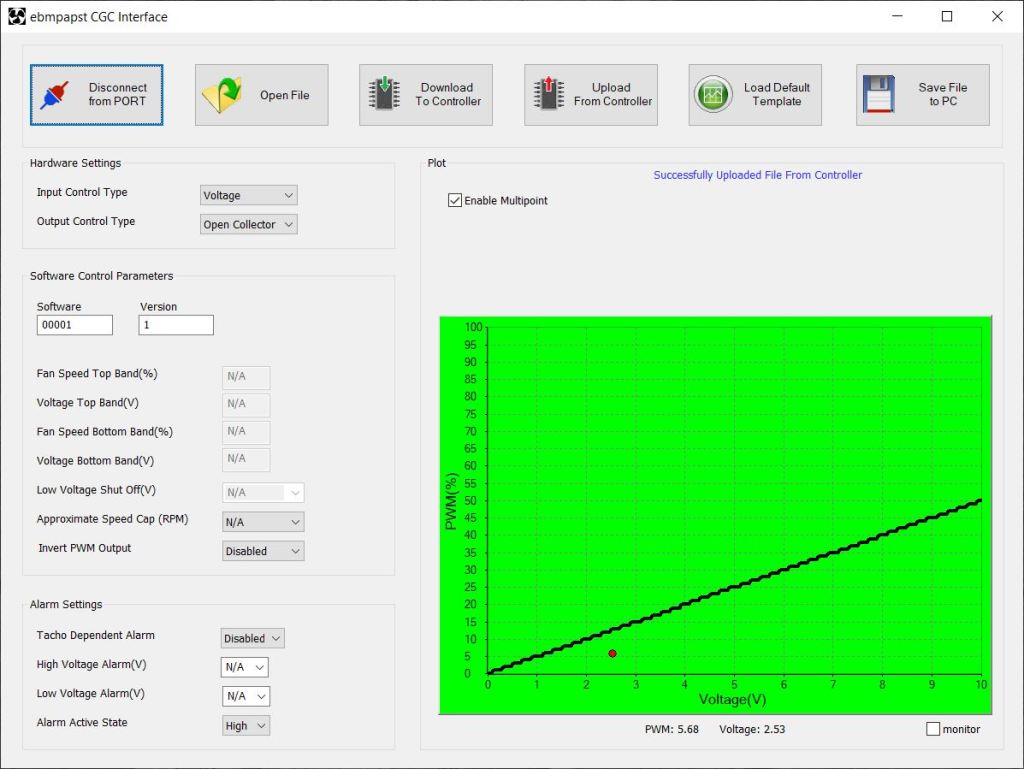
}Papst supplies a Windows-compatible configuration application for their Fan Controller module. It can be used to create custom fan speed maps and ramping profiles.
You attach the Fan Controller to a PC using a supplied custom USB cable which you can use to read and write mappings to the device.
Our default map ramps the fan speed linearly from 0 up to 50% maximum speed at 10V. Each Fan Controller can control up to 16 fans, and there are 4 PCM Analogue output channels, so that’s a maximum of 64 fans in this configuration without additional circuits.
Step 7: Programming
Programming the PMC is done by connecting the micro-USB connector mounted on the front of the PCB to the PC running the Arduino IDE. This provides sufficient power to flash the chip and test the code without the 24V supply. The USB cable is not supplied with the product.
You select the Portenta core in the IDE and the port it is connected to before uploading the binary. Any serial output is displayed in the Serial Monitor of the IDE.
There’s also an option to install Lauterbach’s powerful TRACE32 debugger software after obtaining a free licence key by registering your product.
Summary
The Portenta Machine Control is designed to enhance the intelligence of your products by adding Industrial IoT capabilities to standalone industrial machinery. It enables real-time data collection from the factory floor and supports the remote control of equipment from LAN or cloud.
This project has shown how to add remote sensing from an MQTT server to a fan control system using the PMC’s Analogue Outputs, which is just one example of the many capabilities of the Portenta Machine Control.
The full project code is available for download from the OKdo GitHub repo.
Portenta Machine Control is very well documented and comes with an ever-expanding list of example code – for further details, visit the Arduino product page.
Like what you read? Why not show your appreciation by giving some love.
From a quick tap to smashing that love button and show how much you enjoyed this project.

