For robotics and automation projects using servos, the Pi 4 can act as a powerful processing “brain” to control a separate PWM driver board, attached to many, even hundreds of servos using Python.
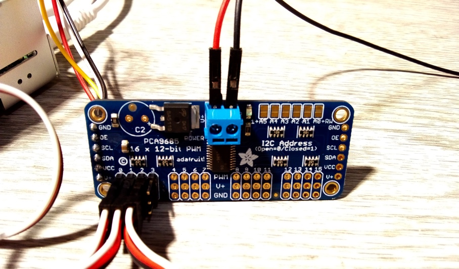
There are several PWM driver boards available and this project uses a 16-channel, 12-bit PWM board with PCA9685 chip and I2C interface. Each board can control up to 16 servos and up to 62 boards can be chained together for a maximum of 996 servos. The board gives glitch-free, 12-bit resolution control of each servo using the Pi4’s I2C bus, leaving other GPIO pins free to use. Both Standard and Continuous servos can be connected.
1. Get your Pi ready
- You should start with a WiFi-enabled Raspberry Pi connected to mouse, keyboard and monitor, you can learn here how to do it using an Okdo Pi kit.
Powering the servo driver
The Servo Driver board uses I2C protocol to communicate with the Pi4. This uses the set of pins down either end of the board to connect to the I2C pins on the Pi4. It operates at 3.3V.
A separate power supply to the board must be used for the servos operating at 5V. This needs to be powerful enough to source sufficient current for the number of servos connected. Each board can support up to 16 servos. This project used 3 servos, each with a maximum current of 140mA (140mA x 3 = 420mA) so a 1A supply was used.
Do not connect the V+ pin on the ends of the servo board to the 3.3 pin on the Pi4 or you will damage your Pi4!
3. Connect the servo driver
Ensure that that the Pi4 is powered off and the servo power supply is disconnected before building or changing the circuit.
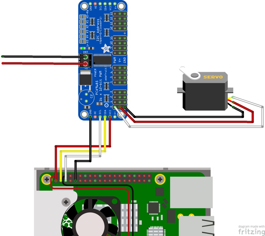
- Pi 4 to Servo Driver connections:
- Connect a female-female jumper from GPIO pin 01 (3.3V) to Servo Driver pin VCC (red)
- Connect a female-female jumper from GPIO pin 03 (SDA) to Servo Driver pin SDA (yellow)
- Connect a female-female jumper from GPIO pin 05 (SCL) to Servo Driver pin SCL (white)
- Connect a female-female jumper from GPIO pin 09 (GND) to Servo Driver pin GND (black)
- Connect each servo to the output pins on the servo driver making sure they are the right way round
- Servo to Servo Driver connections:
- Servo GND pin to Servo Driver GND pin (black)
- Servo 5V pin to Servo Driver V+ pin (red)
- Servo PWM pin to Servo Driver PWM pin (white)
- Connect the 5V power supply to the screw terminal on the Servo Driver
- Power supply to servo driver connections:
- Power supply 5V to Servo Driver V+ (red)
- Power supply GND to Servo Driver GND (black)
Always double check each connection before powering on the Pi4 and switching on the servo power supply.
4. Control servos with Python
The servos in this project use a PWM signal of varying pulse duration to control the position of the servo motor.
The code example uses the Python SMBus module which is included with the default Raspbian install. This is used to send a series of bytes using I2C protocol to the servo driver’s PCA9685 chip registers. By setting the various registers the board modulates the PWM signal to each server and sets its position.
Note: View the PCA9685 datasheet to see details of each register function.
The servo datasheet shows that the servos operate at a PWM frequency of 50Hz (20ms pulse frequency). A pulse duration of 1.5ms is required for the Standard & Continuous servos to set the centre position.
Initially the board PWM frequency pre-scale register is set to 50Hz using the equation from the PCA9685 datasheet for an Oscillator Clock of 25MHz. (25MHz / (4096 x 50Hz)) – 1 = 122 (0x7A).
Note: An oscilloscope was used to tweak this value to exactly 50Hz so a value of 0x08 is used.
Once the PWM frequency has been set, each servo is given a pulse start time of zero and then different durations are set in the loop to move each servo, depending on pulse duration.
Standard Servos can move either clockwise or anti-clockwise up to 90 degrees from the central position. Continuous Servos can rotate continuously in one direction or the other at different speeds, depending on pulse duration.
Note: Pulse durations are calculated and converted to Hex values using the following :(4096 x duration / 20ms) – theoretical values are adjusted in the code for each servo by testing.
Open the Geany IDE from the Main Menu > Programming > Geany and copy and paste the code below into a new tab.
The example code drives each Standard Servo through 180 degrees in 3 steps and each Continuous Server first to the stationary position, then clockwise and anti-clockwise at full speed.
# Servo demo
import smbus
import time

BOARD_I2C_ADDR = 0x40
CHANNEL_0_START = 0x06
CHANNEL_0_END = 0x08
CHANNEL_1_START = 0x0A
CHANNEL_1_END = 0x0C
CHANNEL_2_START = 0x0E
CHANNEL_2_END = 0x10
MODE1_REG_ADDR = 0
PRE_SCALE_REG_ADDR = 0xFE

bus = smbus.SMBus(1)

# Enable prescaler change
bus.write_byte_data(BOARD_I2C_ADDR, MODE1_REG_ADDR, 0x10)

# Set prescaler to 50Hz from datasheet calculation
bus.write_byte_data(BOARD_I2C_ADDR, PRE_SCALE_REG_ADDR, 0x80)
time.sleep(.25)

# Enable word writes
bus.write_byte_data(BOARD_I2C_ADDR, MODE1_REG_ADDR, 0x20)

# Set channel start times
bus.write_word_data(BOARD_I2C_ADDR, CHANNEL_0_START, 0)  # 0us
bus.write_word_data(BOARD_I2C_ADDR, CHANNEL_1_START, 0)
bus.write_word_data(BOARD_I2C_ADDR, CHANNEL_2_START, 0)

while True:
    # Set Standard servos to 0 degrees - 0.5ms pulse
    bus.write_word_data(BOARD_I2C_ADDR, CHANNEL_0_END, 115)
    bus.write_word_data(BOARD_I2C_ADDR, CHANNEL_1_END, 115)
    # Set Continuous servo to stationary - 1.5ms pulse
    bus.write_word_data(BOARD_I2C_ADDR, CHANNEL_2_END, 312)
    time.sleep(5)  # Delay 5 seconds

    # Set Standard servos to 90 degrees - 1.5ms pulse
    bus.write_word_data(BOARD_I2C_ADDR, CHANNEL_0_END, 305)
    bus.write_word_data(BOARD_I2C_ADDR, CHANNEL_1_END, 305)
    # Set Continuous servo to fast clockwise - 1.3ms pulse
    bus.write_word_data(BOARD_I2C_ADDR, CHANNEL_2_END, 265)
    time.sleep(5)

    # Set Standard servos to 180 degrees - 2.5ms pulse
    bus.write_word_data(BOARD_I2C_ADDR, CHANNEL_0_END, 490)
    bus.write_word_data(BOARD_I2C_ADDR, CHANNEL_1_END, 490)
    # Set Continuous servo to fast clockwise - 1.7ms pulse
    bus.write_word_data(BOARD_I2C_ADDR, CHANNEL_2_END, 345)
    time.sleep(5)
5. Do more
- Adjust the speed with which the servos move by using smaller increments in the code.
- Add further servos using the datasheet to find the start and end register addresses. These are listed as LEDn_ON_L and LEDn_OFF_L (PCA9685 can also be used to drive LEDs). Adjust servo power supply requirements accordingly.
- Create Python functions to map angles of rotation to calculate the values sent to the registers. This may make it easier to re-use code in a more complicated project. There are also code libraries that do this but some may not work with the Pi4 until they have been fixed.
Summary
Servo motors are used in many robotics and automation projects where precise control and holding torque are required. They use PWM control signals to operate but the Pi4 only has a single PWM output so it is limited to controlling a single servo. By adding a separate dedicated driver board, the Pi4 can be used as a controller for many, even hundreds of servos.
This project shows how to use Python code to control an I2C servo driver over the Pi4’s I2C bus. It provides example code and shows how to calculate register values using information from the datasheets and how this can be implemented.
Using this information you should be able to build these components into projects of your own or to adapt the code to match different servo driver boards and servos.
Datasheets:
Standard Servo – 900-00005.pdf
Continuous Servo – 900-00008.pdf
Like what you read? Why not show your appreciation by giving some love.
From a quick tap to smashing that love button and show how much you enjoyed this project.

