In this project, you’ll learn how to make an E1 fan controller using the free software library PINT and CTIMER drivers to detect button presses and generate PWM control signals. These are presented in the context of a development application to drive a powerful, PAPST industrial 4 wire fan unit. The application has 3 speed settings controlled by the E1 buttons which drive the fan’s speed.
If you only have the E1 board, you can still build the software and test the buttons and PWM output signal using an oscilloscope.
1. Install MCUXpresso IDE
E1 development is fully supported using the MCUXpresso IDE from NXP. Detailed steps of how to install the IDE and SDK on your host PC are given in the E1 Getting Started guide which is here.
- Follow steps 1 & 2 from the guide until the IDE and SDK are installed on your PC
- Open the IDE ready to start a new project
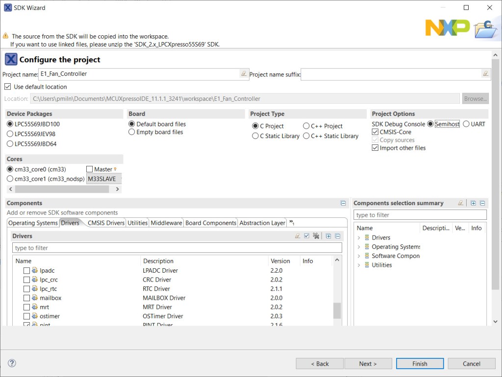
2. Start a new project
- In the Quickstart panel of the default view, select New Project.
- From the SDK Wizard choose the LPCXpresso55S69 board; this SDK is compatible with the E1 board as they both feature the LPC55S69 MCU.
- Click Next to configure the project.
- Change the name of the project, for example, E1_Fan_Controller.
- In the Components section select ctimer, pint and inputmux drivers. Other settings can be left as defaults.
- Click Finish
A new project will be created, and the source files copied into a directory under your workspace.
- The developer view will open with the source file containing the main() function open in the editor. This will be named E1_Fan_Controller.c
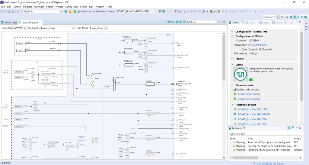
3. System clock configuration
MCUXpresso Clocks Tool can be used to set the System Clock to the correct frequency for the E1 board. Full details of how to set the system clock on the E1 can be found in this tutorial.
The default project sets the System Clock at 150MHz for use with an external 32MHz crystal source via the Phase-locked Loop (PLL). The E1 board does not have the 32MHz external crystal fitted, so this setting cannot be used.
- From the Toolbox icon in the Project tab select Open Clocks.
The clocks view will open showing the clock configuration.
- Click the Clocks Diagram tab to show a graphical view.
- From the Functional Groups dropdown, choose the 96MHz Free Running Oscillator setting – BOARD_BootClockFROHF96M.
- Click the Green Flag icon next to the Functional Group dropdown.
- Select Update Code.
The system clock is now set at 96MHz driven from the 96MHz FRO. The IDE will return to the developer view.
4. Pin configuration
MCUXpresso pins tool can be used to configure the CTIMER mapping to the LEDR pin which generates a PWM output signal. Interrupts can be set on the E1 buttons to detect button presses. The pins tool will generate the source code to include in the build.
Pin mappings for the project:
| Name | Function | Board Pin |
| red LED | PIO1_4 | LEDR |
| ISP button | PIOO_5 | PIOO_5 |
| user button | PIO1_9 | PIO1_9 |
| wake button | PIO1_18 | WAKE |
- From the toolbox icon in the Project Explorer tab select Open Pins.
The Pin Configuration view will open, displaying the default pin settings.
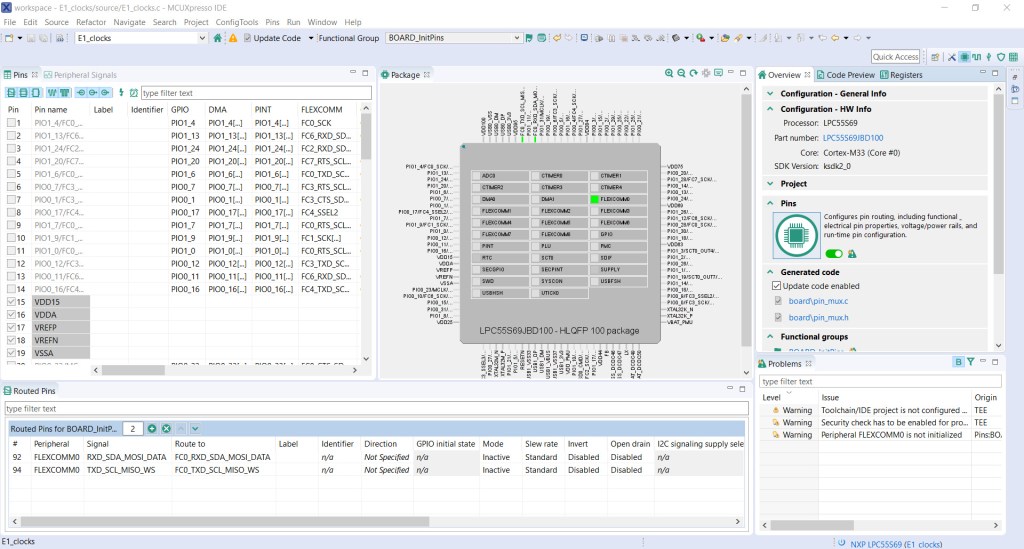
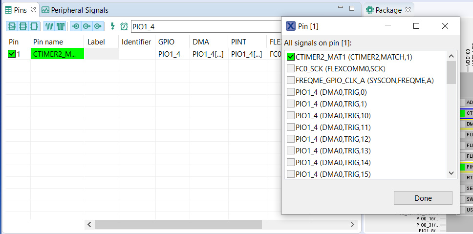
- Enter PIO1_7 in the search box to find the LEDR pin (Pin 1 on the LPC55S69).
- Select Pin 1 to open the pin signals dialogue.
- Select CTIMER2_MAT1.
- Click Done.
Pin LEDR on the E1 board is now mapped to CTIMER2.
- Enter PIO0_5 in the search box to find the PIO0_5 button. (Pin 88 on the LPC55S69)
- Select Pin 88 to open the pin signals dialogue.
- Select PINT,PINT0.
- Click Done.
PIO0_5 button on the E1 board is now mapped to PINT0.
- Repeat the above for PIO1_9 to map PIO1_9 button to PINT,PINT1.
- And PIO1_18 to map WAKE button to PINT,PINT2.
- From the top of the pins view, select Update Code to generate the source code to be included in the project.
- Click OK.
Pins tool will generate the configuration code in pin_mux.h / pin_mux.c.
The IDE will return to the developer view once the source code has been updated.
5. Build & test
The project can now be built and tested using the built-in debugger. The PWM output can be checked using an oscilloscope connected to the LEDR output pin and GND on the E1.
- Enter the code below into E1_Fan_Controller.c, overwriting the existing code.
/*
 * Copyright 2016-2020 NXP
 * All rights reserved.
 *
 * Redistribution and use in source and binary forms, with or without modification,
 * are permitted provided that the following conditions are met:
 *
 * o Redistributions of source code must retain the above copyright notice, this list
 *   of conditions and the following disclaimer.
 *
 * o Redistributions in binary form must reproduce the above copyright notice, this
 *   list of conditions and the following disclaimer in the documentation and/or
 *   other materials provided with the distribution.
 *
 * o Neither the name of NXP Semiconductor, Inc. nor the names of its
 *   contributors may be used to endorse or promote products derived from this
 *   software without specific prior written permission.
 *
 * THIS SOFTWARE IS PROVIDED BY THE COPYRIGHT HOLDERS AND CONTRIBUTORS "AS IS" AND
 * ANY EXPRESS OR IMPLIED WARRANTIES, INCLUDING, BUT NOT LIMITED TO, THE IMPLIED
 * WARRANTIES OF MERCHANTABILITY AND FITNESS FOR A PARTICULAR PURPOSE ARE
 * DISCLAIMED. IN NO EVENT SHALL THE COPYRIGHT HOLDER OR CONTRIBUTORS BE LIABLE FOR
 * ANY DIRECT, INDIRECT, INCIDENTAL, SPECIAL, EXEMPLARY, OR CONSEQUENTIAL DAMAGES
 * (INCLUDING, BUT NOT LIMITED TO, PROCUREMENT OF SUBSTITUTE GOODS OR SERVICES;
 * LOSS OF USE, DATA, OR PROFITS; OR BUSINESS INTERRUPTION) HOWEVER CAUSED AND ON
 * ANY THEORY OF LIABILITY, WHETHER IN CONTRACT, STRICT LIABILITY, OR TORT
 * (INCLUDING NEGLIGENCE OR OTHERWISE) ARISING IN ANY WAY OUT OF THE USE OF THIS
 * SOFTWARE, EVEN IF ADVISED OF THE POSSIBILITY OF SUCH DAMAGE.
 */

#include <stdio.h>
#include "board.h"
#include "peripherals.h"
#include "pin_mux.h"
#include "clock_config.h"
#include "LPC55S69_cm33_core0.h"
#include "fsl_debug_console.h"
#include "fsl_ctimer.h"
#include <stdbool.h>
#include "fsl_pint.h"
/*******************************************************************************
 * Definitions
 ******************************************************************************/
// PWM
#define CTIMER CTIMER2                 /* Timer 2 */
#define CTIMER_MAT_OUT kCTIMER_Match_1 /* Match output 1 */
#define CTIMER_CLK_FREQ CLOCK_GetCTimerClkFreq(2U)
// Fan Speeds - Duty Cycle %
#define OFF 0U
#define LOW 20U
#define HIGH 40U
/*******************************************************************************
 * Variables
 ******************************************************************************/
volatile uint8_t g_state = 0U; // Fan state 0, 1, 2
volatile uint8_t g_pwmDutyCyclePercent = 100U;
volatile uint32_t g_pwmPeriod   = 0U;
volatile uint32_t g_pulsePeriod = 0U;
/*******************************************************************************
 * Code
 ******************************************************************************/
status_t CTIMER_GetPwmPeriodValue(uint32_t pwmFreqHz, uint8_t dutyCyclePercent, uint32_t timerClock_Hz)
{
    /* Calculate PWM period match value */
    g_pwmPeriod = (timerClock_Hz / pwmFreqHz) - 1;

    /* Calculate pulse width match value */
    if (dutyCyclePercent == 0)
    {
        g_pulsePeriod = g_pwmPeriod + 1;
    }
    else
    {
        g_pulsePeriod = (g_pwmPeriod * (100 - dutyCyclePercent)) / 100;
    }
    return kStatus_Success;
}

/*!
 * @brief Call back for PINT Pin interrupt 0-7.
 */
void pint_intr_callback(pint_pin_int_t pintr, uint32_t pmatch_status)
{
	g_state = pintr;
}

/*!
 * @brief Set fan speed according to system state triggered by pintr.
 */
void updateFanSpeed(uint8_t state)
{
    uint8_t fanSpeed;

	switch(state){
	case 0: // ISP
		fanSpeed = OFF;
		break;
	case 1:  // USER
		fanSpeed = LOW;
		break;
	case 2:  // WAKEUP
		fanSpeed = HIGH;
	}
	g_pwmDutyCyclePercent = 100 - fanSpeed;  // Invert duty cycle percentage
	PRINTF("rnFan speed: %d%%", fanSpeed);
	CTIMER_UpdatePwmDutycycle(CTIMER, CTIMER_MAT_OUT, g_pwmDutyCyclePercent);
}
/*
 * @brief   Application entry point.
 */
int main(void) {
    ctimer_config_t config;
    uint32_t srcClock_Hz;
    uint32_t timerClock;

  	/* Init board hardware. */
    BOARD_InitBootPins();
    BOARD_InitBootClocks();
    BOARD_InitDebugConsole();

    /* Use 12 MHz clock for some of the Ctimers */
    CLOCK_AttachClk(kFRO_HF_to_CTIMER2);

    /* CTimer0 counter uses the AHB clock, some CTimer1 modules use the Aysnc clock */
    srcClock_Hz = CTIMER_CLK_FREQ;

    CTIMER_GetDefaultConfig(&config);
    timerClock = srcClock_Hz / (config.prescale + 1);

    CTIMER_Init(CTIMER, &config);

    /* Setup CTIMER match for 1kHz PWM signal with 100% dutycycle */
    CTIMER_GetPwmPeriodValue(1000, g_pwmDutyCyclePercent, timerClock);
    CTIMER_SetupPwmPeriod(CTIMER, CTIMER_MAT_OUT, g_pwmPeriod, g_pulsePeriod, false);
    CTIMER_StartTimer(CTIMER);

    PRINTF("CTimer configured to generate a PWM signalrn");

    /* Initialize PINT */
    PINT_Init(PINT);

    /* Setup Pin Interrupt 0 for rising edge */
    PINT_PinInterruptConfig(PINT, kPINT_PinInt0, kPINT_PinIntEnableRiseEdge, pint_intr_callback);
    /* Enable callbacks for PINT0 by Index */
    PINT_EnableCallbackByIndex(PINT, kPINT_PinInt0);

	#if (FSL_FEATURE_PINT_NUMBER_OF_CONNECTED_OUTPUTS > 1U)
		/* Setup Pin Interrupt 1 for falling edge */
		PINT_PinInterruptConfig(PINT, kPINT_PinInt1, kPINT_PinIntEnableFallEdge, pint_intr_callback);
		/* Enable callbacks for PINT1 by Index */
		PINT_EnableCallbackByIndex(PINT, kPINT_PinInt1);
	#endif

	#if (FSL_FEATURE_PINT_NUMBER_OF_CONNECTED_OUTPUTS > 2U)
		/* Setup Pin Interrupt 2 for falling edge */
		PINT_PinInterruptConfig(PINT, kPINT_PinInt2, kPINT_PinIntEnableFallEdge, pint_intr_callback);
		/* Enable callbacks for PINT2 by Index */
		PINT_EnableCallbackByIndex(PINT, kPINT_PinInt2);
	#endif

    PRINTF("rnPINT Pin Interrupt events are configuredrn");
    PRINTF("rnPress ISP (OFF), USER (LOW), WAKE (HIGH) to set fan speedrn");
    while (1)
    {
        __WFI();
        updateFanSpeed(g_state); // Update fan speed
    }
}
- Plug a micro-USB cable into the Debug socket on the E1 board and connect to the host computer.
- In the Quickstart pane select Build.
The project will build without errors, shown in the Console pane.
- In the Quickstart panel, select Debug to start the debugger.
The IDE will discover the LPC11U3x_CMSIS_DAP debug probe.
- Select OK
- The debugger will detect 2 SWD Devices, one for each of the LPC55S69 cores
- Select OK
- The MCU will be flashed with the system image
- The Debugger will run up to the first line in main() and then suspend.
- Select the Resume (F8) icon to continue running
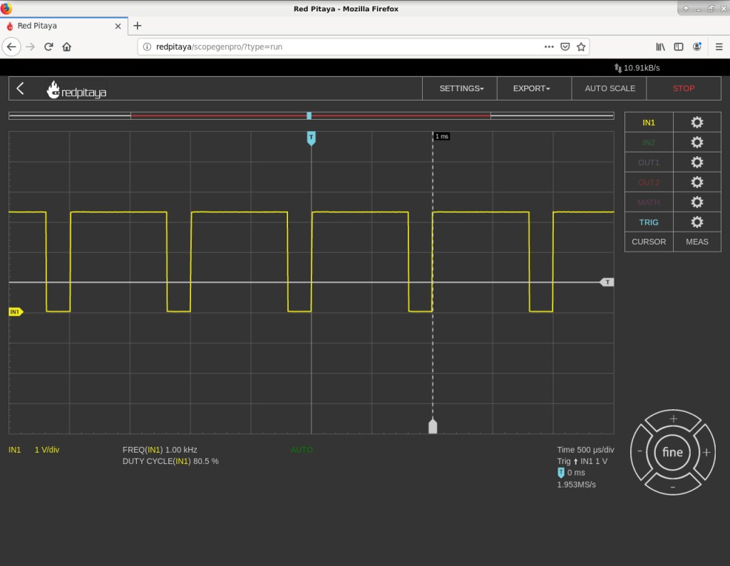
The Printf statements will appear in the Console pane when buttons ISP, USER & WAKE are pressed.
The PWM signal can be seen on the oscilloscope – the signal on the LEDR pin has the duty cycle inverted to control the brightness of the LED correctly. High being OFF and Low being ON.
- End debugging by selecting the Terminate icon (Ctrl + F2).
6. Build the circuit
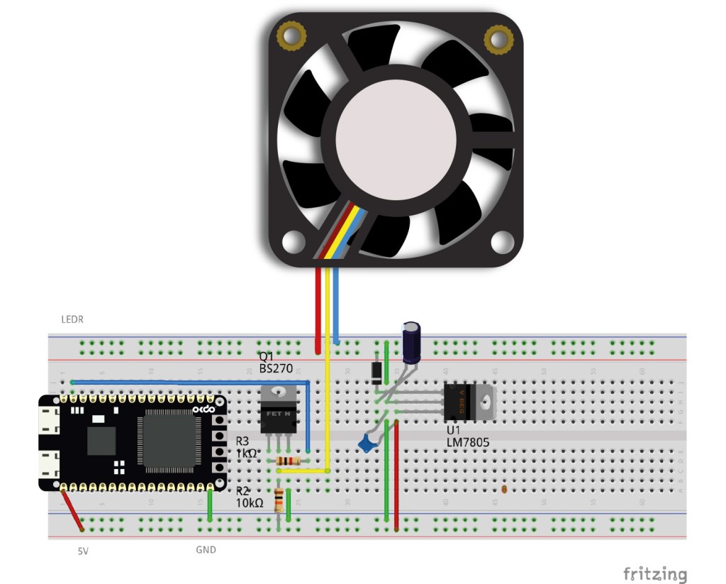
A 30V / 5A DC bench power supply connects to the +24V and GND terminals for the fan. The linear voltage regulator has its input connected to the +24V rail of the fan circuit. A general-purpose diode provides reverse polarity protection and 1uF bypass capacitors provide filtering. The regulators 5V output connects to the 5V rail which powers the E1 via its 5V pin. The E1 GND pin is connected to GND. The E1 has an onboard LDO regulator (Maximum input 6V) that outputs 3.3V to VDD.
E1 pins have a maximum voltage rating of 3.3V – do not connect any higher voltages as this may damage the board.
An N-Channel MOSFET inverts the PWM signal from the LEDR pin. It also isolates the pin from any higher voltages. The LEDR output is connected to the Gate of the MOSFET via a 1k resistor, while a 10k resistor is connected between 5V and Drain. The MOSFET source is connected directly to GND. The Papst fan used in the example requires a 1 – 5kHz PWM signal on its open collector input. This is connected between the Drain of the MOSFET and the 10k resistor. When the Gate of the MOSFET is driven HIGH, the PWM output is driven LOW and vice versa.
The controller has 3 speeds, OFF (ISP), LOW (USER) and HIGH (WAKE) set by pressing one of the E1 buttons. Interrupts connected to the buttons cause the system status to update which changes the PWM duty cycle which controls the fan. Once a button has been pressed, the system then waits for the next interrupt.
Check the pinout of your MOSFET as it may be different from the one shown in the circuit diagram.
Summary
This guide has shown you how to start a new E1 project using MCUXpresso IDE and to use the PINT and CTIMER drivers included in the SDK. The example is used to create an application that drives a PWM controlled fan unit using button interrupts on the E1 board.
We showed how the Clocks and Pins tools built into MCUXpresso IDE can be used to generate pin configuration code to ease development of complex applications and minimise coding. This allows the developer to concentrate on the application logic.
The SDK provides several demo apps that show how to use many other free peripheral drivers that can be used in your own code or as a starting point for applications.
Like what you read? Why not show your appreciation by giving some love.
From a quick tap to smashing that love button and show how much you enjoyed this project.

