This guide will take you through clock configuration on the E1 Board. Setting the clock frequency of the MCU is one of the initial steps in starting a new E1 project or adapting the SDK example projects so that they run on the E1 board. This tutorial will guide you through the steps to configure the System Clock of the E1 in MCUXpresso IDE and to check its frequency using an oscilloscope.
1. Install MCUXpresso IDE
To install MCUXpresso IDE you will need to register for a free NXP developer account. Installers are available for Windows 10, Linux & macOS. The example shows installation on a Windows 10 PC but the steps are similar on the other supported operating systems.
- Visit the MCUXpresso IDE download page.
- Register for a developer account or Log in.
- Download the correct IDE installer for your host PC.
- Once the download has completed, run the installer.
- Accept the EULA and defaults settings along with any security warnings.
- After a few minutes, the IDE User Guide will open in your default browser followed by the IDE Help window and finally the IDE Welcome window.
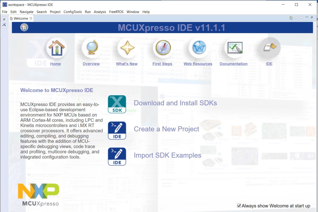
2. Start a new project
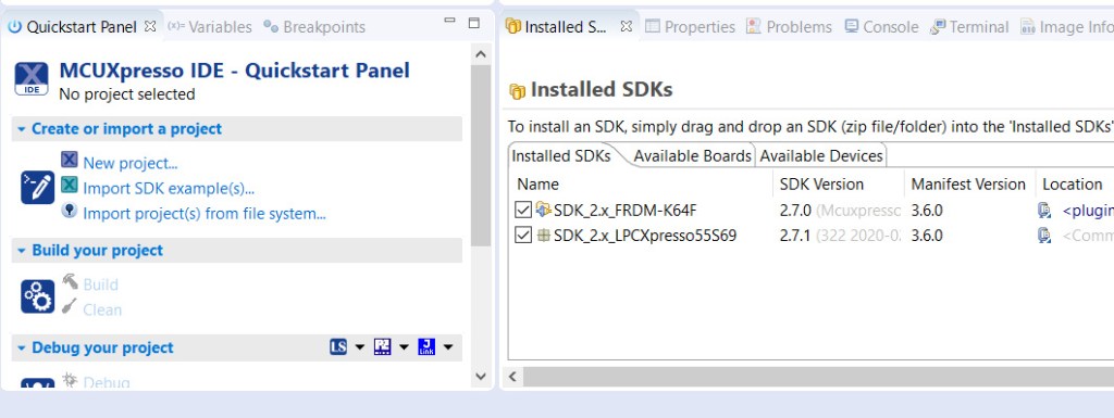
- In the Quickstart panel of the default view select New Project.
- From the SDK Wizard choose the LPCXpresso55S69 board – this SDK is compatible with the E1 board as they both feature the LPC55S69 MCU.
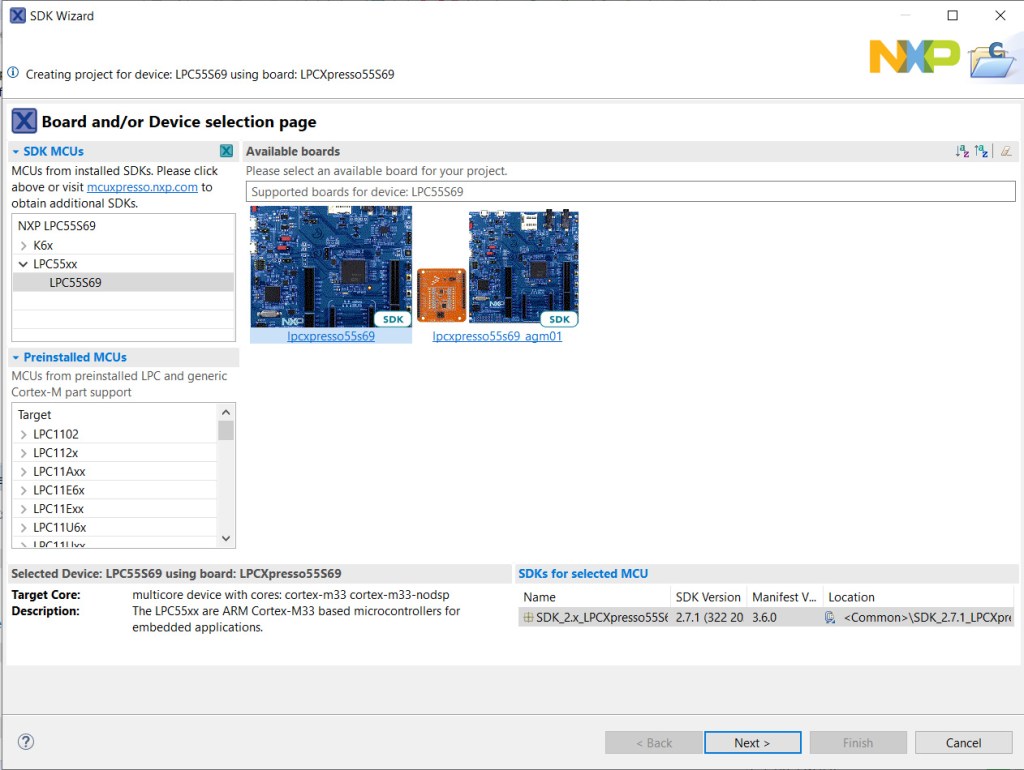
- Click Next to configure the project.
- Change the name of the project. For example, E1_clocks
- All other options can be left as defaults
E1 has the LPC55S69JBD100 package on board. This project requires a single core (CM33_core0).
Only the default drivers are required for this project – you can always add drivers later during the developments cycle if required.
- Click Next.
A new project will be created, and all the source files copied into a directory under your workspace.
- The developer view will open with the source file containing the main() function open in the editor.
- main() contains boiler-plate code for a simple project which will compile at this point.
3. System clock configuration
The system clock requires setting to the correct frequency for the E1 board.
The default project sets the system clock at 150MHz using an external 32MHz crystal source via the Phase-locked Loop (PLL). The E1 board does not have the 32MHz external crystal fitted, so this setting cannot be used.
- From the Toolbox icon in the Project tab select Open Clocks.
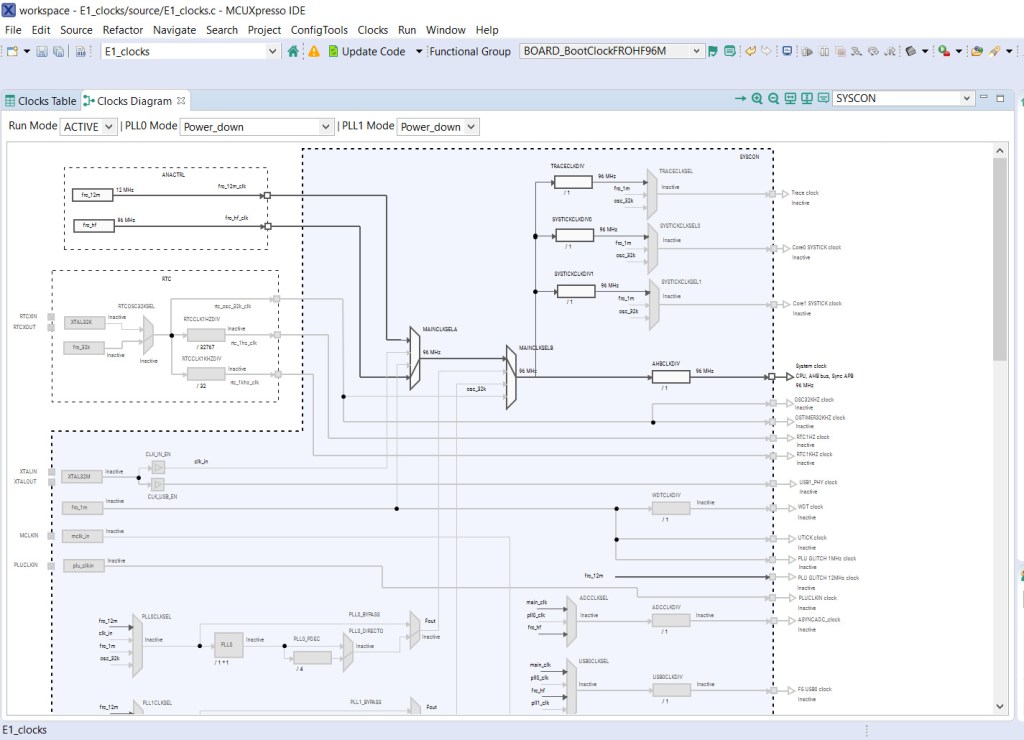
- The clocks view will open, this shows the clock configuration settings for the Default Project.
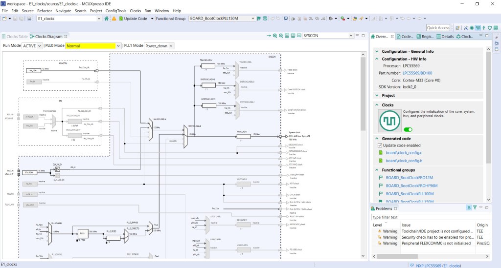
- Click the Clocks Diagram tab to show a graphical view.
The SDK comes with several pre-defined Functional Group settings that will configure the clocks correctly and generate source code automatically.
- From the Functional Groups dropdown in the clocks view choose the 96 MHz High Frequency Free Running Oscillator setting – BOARD_BootClockFROHF96M.
- Click the Green Flag icon next to the Functional Group dropdown; this makes the setting the default.
- The system clock is now set at 96MHz driven from the 96MHz HF FRO. The configuration path is shown highlighted in the view.
4. Clock out configuration
The system clock signal is available on the clock out (CLKOUT) pin of the LPC55S69 MCU. To check the CLKOUT frequency a clock divider will be used to reduce the signal frequency so that it can be measured accurately using an oscilloscope.
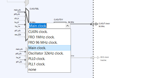
- In the Clocks Diagram select the CLKOUTSEL multiplexer and set its source to Main Clock.
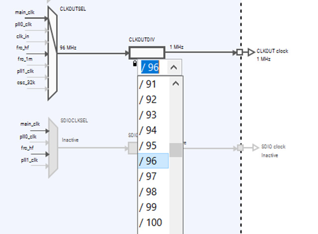
- Select the CLKOUTDIV and divide the CLKOUT clock by 96 to set a frequency of 1MHz.
Finally, use the Clocks Tool to generate the clock configuration source code in the project using these settings:
- Select the Update Code item from the top of the Clocks Perspective.
- Select OK to accept the updates.
- The IDE will return to the developer view when the clocks configuration source code has been generated.
- The System Clock is now set to 96MHz and the Clock Out signal is set to 1MHz.
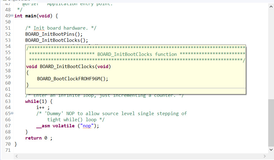
- Hover over the BOARD_InitBootClocks() function in the developer view to see the default setting.
5. Pin configuration
Now that the system clock is set up for the E1 Board, the CLKOUT signal can be multiplexed to one of the I/O pins so that it can be measured using an oscilloscope.
From the LPC55S69 User Manual https://www.nxp.com/webapp/Download?colCode=UM11126 the CLKOUT function is available on MCU pin PIO0_16, which is Pin 2 on the X100 Expansion connector of the E1.
The Pins Tool in MCUXpresso IDE can be used to map pin functions on the MCU to the I/O connectors on the E1 board. The Pin tool will generate the source code that is included in the project.
- From the Toolbox icon in the Project Explorer tab select Open Pins.
- The Pin Configuration view will open displaying the default pin settings.
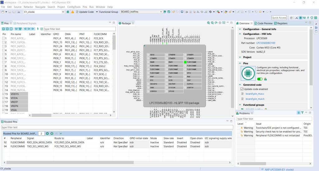
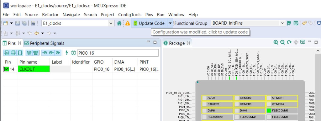
- Enter PIO0_16 in the Search Box to find the required pin.
- Select Pin 14 and the pin signals for that pin will be displayed in the dialogue box.
- Select CLKOUT to Route the CLKOUT signal to pin 14 of the MCU.
- From the top of the Pins view, select the Update Code item to generate the source code to be included in the project.
- Select OK.
The IDE will return to the Developer view once the source code has been updated. Pin 2 on the E1 X100 connector is now mapped to the 1MHz CLKOUT signal, divided down by 96 from the 96MHz System Clock.
6. Build & run the project
The project can now be built and run using the built-in debugger so that the CLKOUT signal can be measured.
- Plug a micro-USB cable into the Debug socket on the E1 board and connect to the host PC.
- The Red Power LED on the E1 board will turn on.
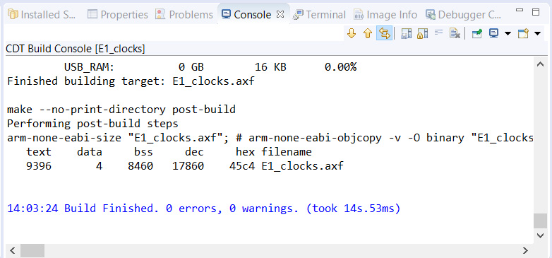
- In the Quickstart pane select Build.
- The project will build without errors, shown in the Console pane.
- In the Quickstart panel, select Debug to start the debugger.
The IDE will discover the LPC11U3x_CMSIS_DAP debug probe
- Select OK
- The MCU will be flashed with the system image
The debugger will run-up to the first line in main() and then suspend. This is the default behaviour of the debugger.
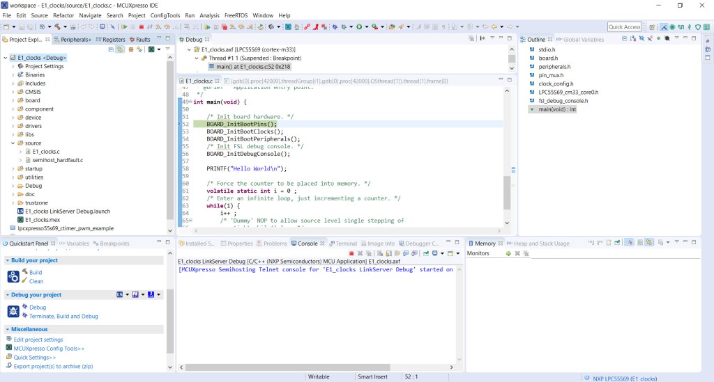
- Select the Resume (F8) icon to continue running.
The Printf statement will appear in the console pane.
- End debugging by selecting the Terminate icon (Ctrl + F2).
The code will continue to run even when the debug session has ended.
7. Measure CLKOUT
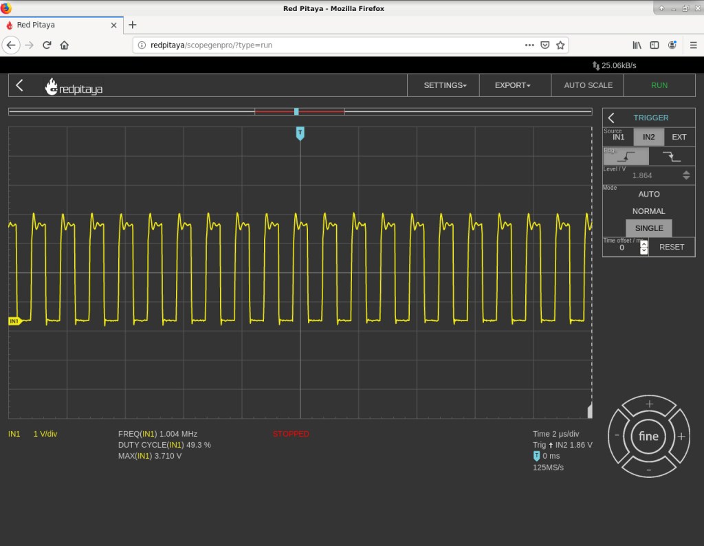
The CLKOUT signal frequency can now be measured using an oscilloscope.
- Connect ground of the oscilloscope probe to X100 Pin 16 (GND) and probe X100 Pin 2 (CLKOUT)
- The trace will display the 1MHz CLKOUT signal divided by 96 from the System Clock set at 96MHz
Summary
This guide has shown how to start a new E1 project using MCUXpresso IDE and configure the system clock using the clocks tool. The CLKOUT signal was then multiplexed and divided down so that it could be output to one of the I/O pins on the E1 board.
The MCU was set to run at 96MHz so the clock signal was divided by 96 to output a 1MHz signal which could be measured using an oscilloscope. The oscilloscope trace validated that the System Clock was running at the expected frequency.
You should now be able to configure the System Clock on the E1 using the MCUXpresso IDE for use in your own projects or adjust the settings for the SDK examples so that they run on the E1 board.
Like what you read? Why not show your appreciation by giving some love.
From a quick tap to smashing that love button and show how much you enjoyed this project.

