This project is all about learning how to brew your own beer with Arduino! So, if you’re loving beer and you’d like to learn how to brew beer using technology, follow the steps below to set up a smart home brewery. We show you how to modify a domestic fridge by adding your microcontroller temperature controller to create the perfect brewing environment and obtain great beer brewing equipment.
We used an Arduino Opla connected to digital temperature sensors to control the fridge compressor and added a small heater to keep your beer warm enough when fermenting. The controller connects to your local network using wifi for logging the temperature profile of your brew as it’s progressing, and there’s a dashboard display so you can carefully monitor your brewing process.
If you’re wondering how long does it take to brew beer, please note that this project walks you only through the steps of setting up the home brewery and should take about 6 hours to complete. However, the brewing process itself takes additional time. Beer then should brew for almost 10 days. We will update this project once our OKbrew will be ready bottled.
Warning: Care needs to be taken when dealing with mains voltages – if you are not sure about this, consult a qualified electrician.
Step 1: Arduino Opla
The Arduino Opla is a great kit to base the Beer Controller on. It’s quite capable of monitoring a couple of temperature sensors in real-time and has two built-in relays for actuating switches. With an MKR1010 module on board, connecting to your local network means you can keep an eye on the progress of your brew from any device and record its temperature profile over time.
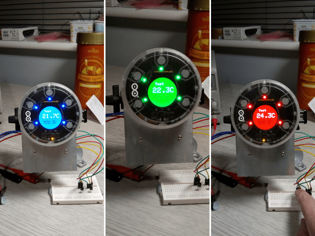
It’s also got a nice OLED display for showing the beer temperature in traffic light colours, LED’s connected to the relays to show their status. The whole unit is enclosed in a plastic case that’s practical and good looking.
We used the touch-sensitive buttons on the front of the unit to create a menu of brewing processes for fermenting and finishing, each one having a different temperature profile. The menu is presented when the Opla starts, and you choose a brewing process. Once this is saved, the device switches into monitoring mode, where it samples both a beer and air digital thermometer and controls the heater and cooler in the fridge, keeping your brew at just the right temperature.
Temperature data and heater / cooler states are sent via an MQTT client running on the Opla to a remote server running an MQTT / InfluxDB / Telegraf / Grafana stack to record the brews progress and for dashboard monitoring from any device.
Step 2: Temperature sensors
A pair of Maxim Integrated DS18B20 digital thermometers measure the beer and air temperature inside the fridge. These are accurate to +-5 degrees celsius in 9-bit resolution and operate using a one-wire bus.
Each sensor has a separate +3.3V power, and ground connection with a shared data line pulled up to +3.3V by a 4.7k Ohm resistor. We soldered telephone wire to each sensor insulating the connections with heat shrink tubing and surrounding the end with a second shrink wrap tube.
The Arduino Dallas Temperature library makes it easy to read these sensors using the MKR1010 board, and you can install it into the Arduino IDE from the Library Manager.
To obtain the unique device ID for the thermometers used in the main program, we wired both sensors up to a breadboard and flashed the Tester code that comes with the library. You should see output similar to this in the serial monitor:
Dallas Temperature IC Control Library Demo
Locating devices...Found 2 devices.
Parasite power is: OFF
Found device 0 with address: 2861652405000062
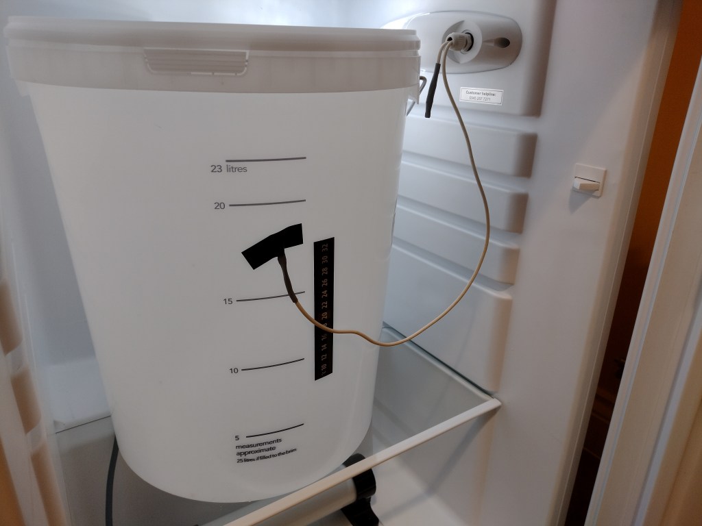
Setting resolution to 9Both sensor cables were routed through the hole where the fridge thermostat was positioned before removing it. We made an access hole in the fridge insulation material and drilled through from inside to meet up with the channel. A cable gland sealed everything in place.
Step 3: Relays
Opla has two built-in relays that can switch up to 24V with software functions to control them and dedicated status LEDs under the display. Because we need to switch 240V AC for the fridge compressor and heater, we couldn’t use them directly but connect them to solid-state relays (SSR’s) rated for that voltage.
Our fridge was rated at 2W / 240VAC and the heater at 45W / 240VAC, so we used 2 TE Connectivity 10A solid state relays as switches. These need a minimum 4VDC switching voltage at 7mA, so we connected the normally open (NO) and Common (C) connections on the Opla relays to the SSR’s. The Opla relays were connected directly to the 5V rail on our breakout board.
Step 4: Fridge control
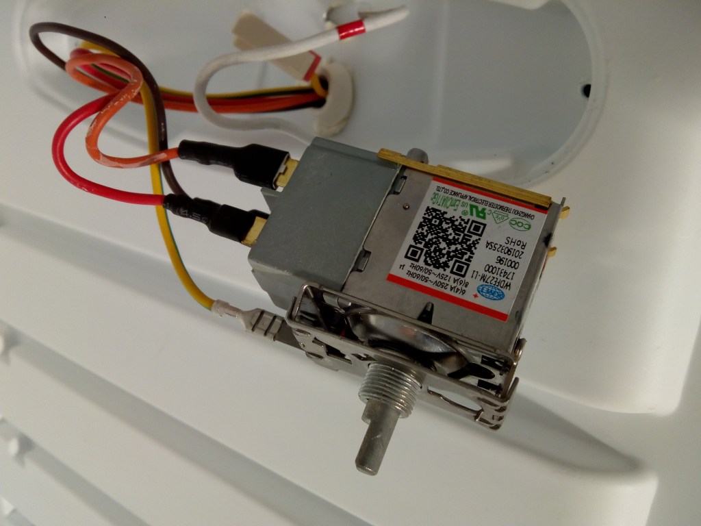
We removed the original fridge thermostat positioned within the light enclosure. It has three connections, Brown (Line in), Orange (Switched line) and Red (Switched line out). The unit contains a switch that isolates the whole fridge and the thermostat switch, which controls the compressor.
We replaced the thermostat by connecting the brown & orange cables. We then connected it to one of the SSR AC terminals. The Red line out was connected to the other AC terminal.
Then we connected 5VDC & GND control cables from one of the Opla relays to the DC terminals on the SSR, taking note of the polarity.
The SSR fitted neatly in the place of the thermostat in the light enclosure, and the door switch still turns the light on and off.
Step 5: Heater control
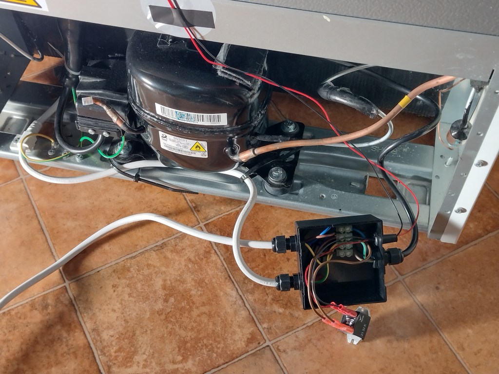
We fitted a 45W Tubular Heater into the base of the fridge with the mains cable being routed through the condensate runoff hole at the back of the fridge, where we could connect it to the mains input.
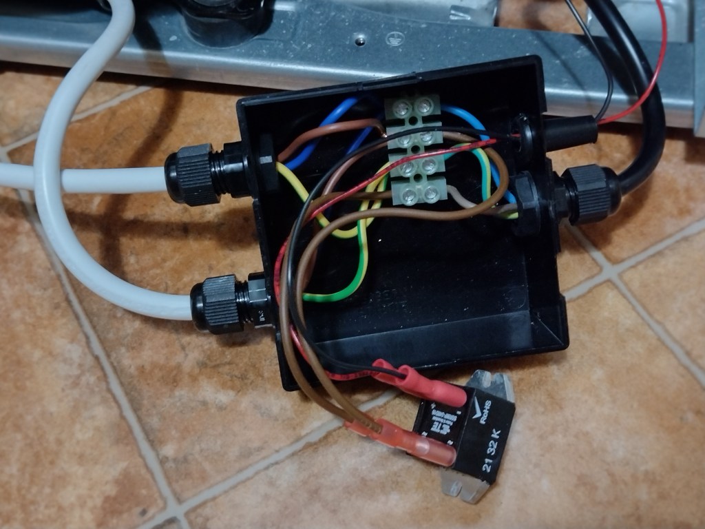
The original fridge mains cable was cut and fed into a junction box, with the heater cable’s Line being connected via the SSR to the Neutral. The terminal block and SSR were fitted into a plastic enclosure with cable glands to isolate them safely.
The 5VDC and GND control wires were routed up the back of the fridge to the Opla breakout board.
Step 6: Breakout board
To connect everything together, we built a simple circuit on a breakout board designed for a Raspberry Pi; conveniently, it had 3.3V and 5V rails. The board holds a 5V linear regulator to power the Opla and drive the SSR DC circuit. There’s a reset button for the MKR1010, the 4K5R pullup resistor for the One-Wire bus and a couple of connectors for the thermometer and relay control wiring.
Here’s the circuit diagram:
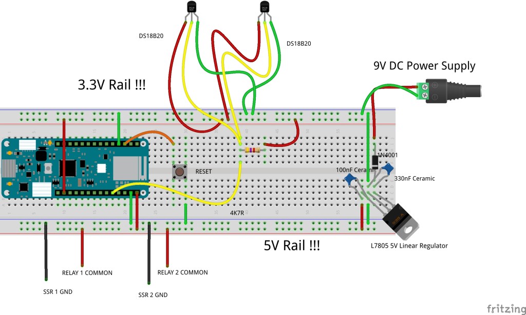
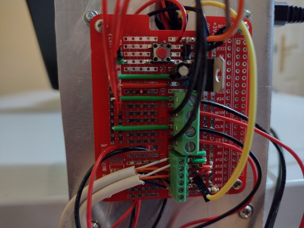
The above process shows how it was connected to the Opla using Dupont wires. The circuit board was mounted on the rear of the Opla support bracket that was cut from 1mm sheet aluminium. The centre connections go to the 2 SSR’s, and the bottom connections go to the digital thermometers:
Step 7: Software
The software running on the MKR1010 inside the Opla was developed in C/C++ using the Arduino IDE environment.
All the source code is available for download from the OKdo Github repository.
The code samples the temperature sensors and switches the relays for the heater and the cooler to keep the beer at a constant set temperature. It also sends output to the OLED display and connects to the local network over WiFi to log data.
Temperature and relay status are sent to a remote MQTT server as a JSON payload running on a Raspberry Pi.
Several challenges need addressing for a monitoring system like this so that if anything goes wrong, your beer is not ruined!
- Accurate temperature readings – resample if readings are out of band
- A safe shutdown of the heater and fridge if the thermometers fail
- Smoothing of discrete readings to avoid switching on and off rapidly at the boundary temperature
- Ensuring you cannot turn on the heater and the cooler at the same time
- Reconnecting to Wifi if connectivity is temporarily lost
- Ensuring that beer monitoring is not interrupted for long periods
We found that the touch-sensitive buttons were difficult to use reliably, so we used two modes. One was where the buttons were active for choosing the menu options, and a second mode was dedicated to beer monitoring without interruption.
Stopping the heater and cooler bouncing on and off was dealt with by collecting several temperature samples and generating a rolling average before testing whether to change the switch state. It seems to be quite effective in keeping the beer at a reasonably constant temperature within the set range.
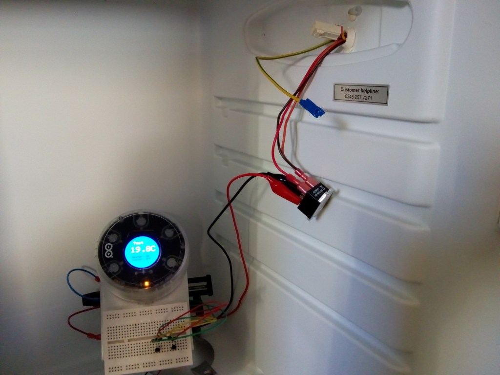
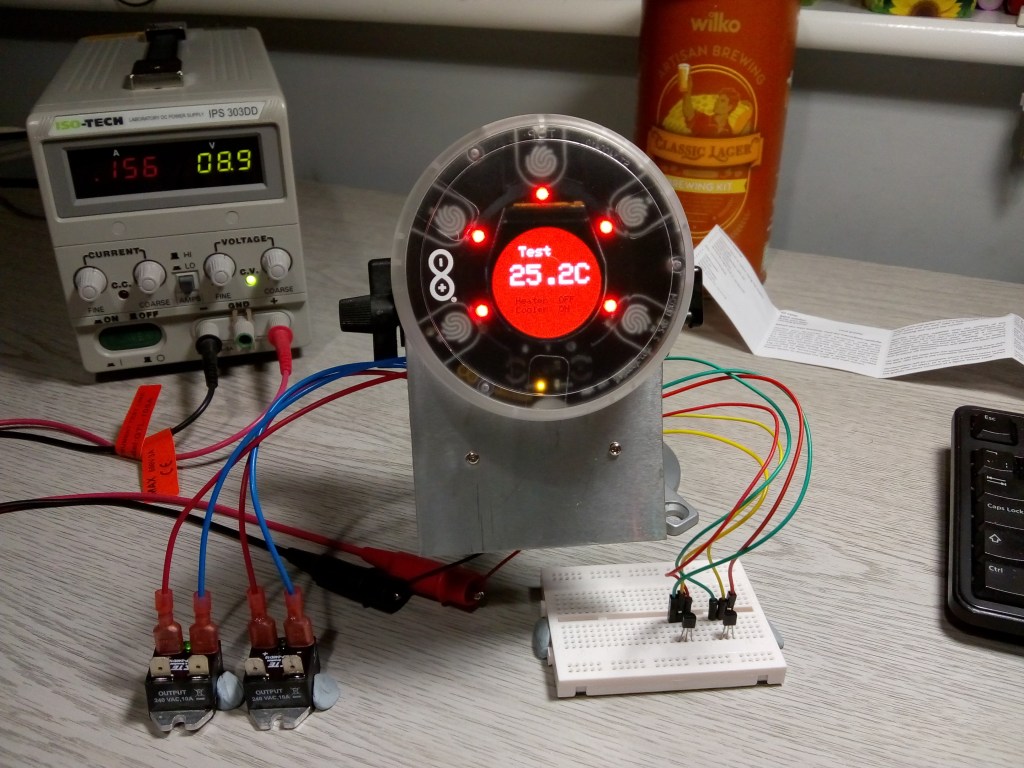
Step 8: Testing
Once we completed the circuit board and wrote the software, we set up the Opla and tested it first on the bench before being tested in situ. The SSR’s have a small LED between the DC terminals that indicate when the switch is closed:
Step 9: Dashboard server
To log the sensor and relay data, we set up a separate remote, headless, Raspberry Pi on the network running MQTT, InfluxDB, Telegraf and Grafana in a similar way to the Cricket Project.
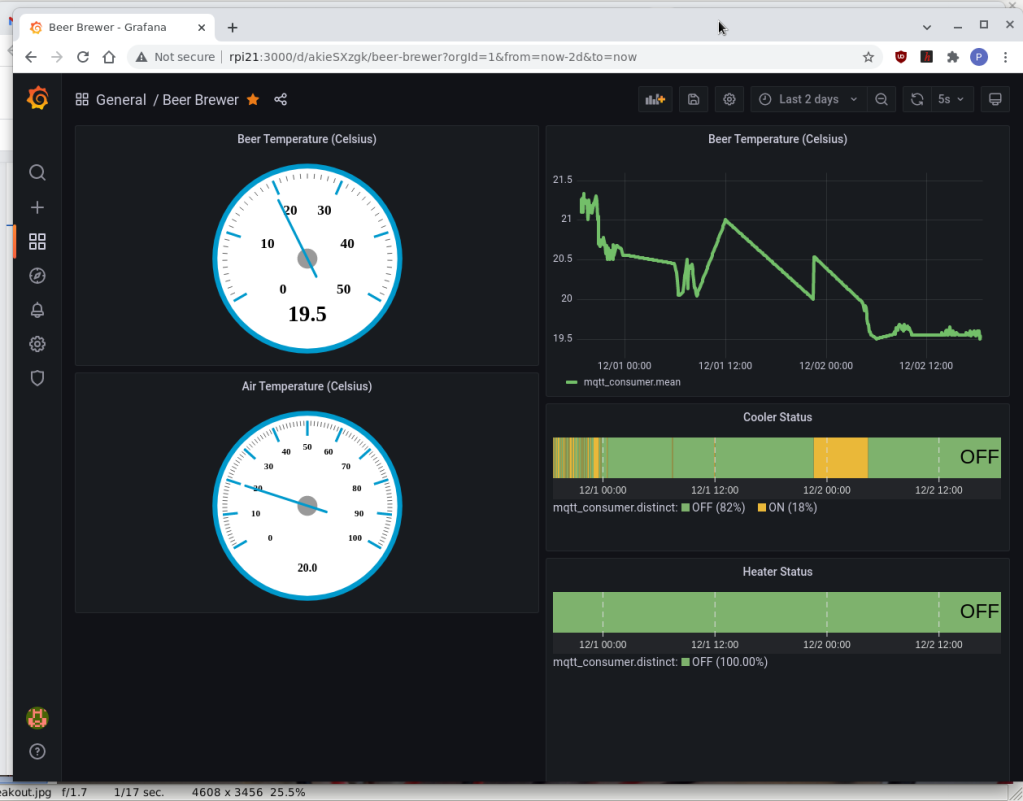
The MQTT server receives the JSON payload containing the sensor data, which is forwarded to the Influx database by Telegraf. The Grafana dashboard is connected to the database and configured to display the current beer temperature, historical time-based temperature and the heater On / Off status.
Step 10: Mosquitto
Use the command line to install the Mosquitto MQTT server package and client tools:
sudo apt install mosquitto mosquitto-clientsStart Mosquitto:
sudo systemctl start mosquitto.serviceTo test that readings are being received from the Opla, run the following command:
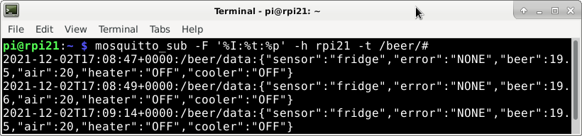
mosquitto_sub -F '%I:%t:%p' -h rpi21 -t /beer/#You should get output similar to the following:
Step 11: InfluxDB
Install and setup influxDB using the command line on the Raspberry Pi:
sudo apt install apt-transport-https
wget -qO - https://repos.influxdata.com/influxdb.key | sudo apt-key add -
source /etc/os-release
test $VERSION_ID = "10" && echo "deb https://repos.influxdata.com/debian buster stable" | sudo tee /etc/apt/sources.list.d/influxdb.list
sudo apt update && sudo apt install influxdb
Start the Influx service:
sudo systemctl start influxdb.serviceStart the influx client, create a database for the readings and add a separate admin user so Grafana will be able to access the data:
influx
create database beer
use beer
create user grafana with password '123456' with all privileges
grant all privileges on beer to grafana
exit
Step 12: Telegraf
Telegraf uses plug-ins to support many different data inputs and outputs. We used the MQTT Consumer input plug-in and the InfluxDB output plug-in to connect the Mosquitto server to the InfluxDB database, so messages are saved each time they are published.
Install Telegraf:
sudo apt install telegrafCreate a default configuration file telegraf.conf in /etc/telegraf
cd /etc/telegraf
sudo sh -c 'telegraf config > telegraf.conf'
Change directory:
cd /etc/telegraf/telegraf.d/Create a file named beer.conf with the following contents. Telegraf defaults to numeric values for JSON format so you need to specify the “string” values. You will need sudo privileges:
[[inputs.mqtt_consumer]]
  # MQTT broker
  servers = ["tcp://localhost:1883"]
  topics = ["/beer/#"]
  qos = 0
  connection_timeout = "30s"
  json_string_fields = ["heater","cooler"]
  data_format = "json"

[[outputs.influxdb]]
  # InfluxDB instance
  urls = ["http://localhost:8086"]
  database = "beer01"
Restart Telegraf:
sudo systemctl restart telegraf.serviceCheck Influx is storing the temperature readings:
influx
use beer
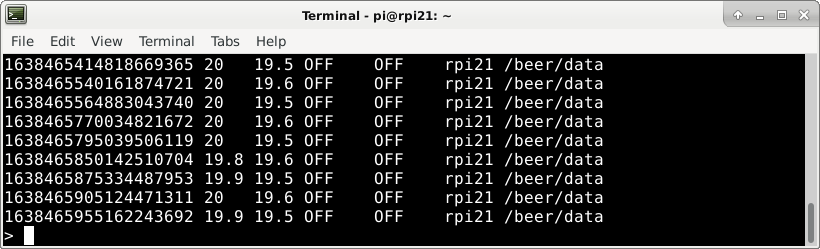
select * from mqtt_consumer
exitYou should get output similar to the following:
Step 13: Grafana
Install Grafana from the command line:
wget -qO - https://packages.grafana.com/gpg.key | sudo apt-key add -
echo "deb https://packages.grafana.com/oss/deb stable main" | sudo tee /etc/apt/sources.list.d/grafana.list
sudo apt update && sudo apt install grafana
Now Reboot the Raspberry Pi.
Set up the Grafana connection to Influx by logging into Grafana and adding a data source in a browser. If your Raspberry Pi hostname is raspberrypi, open the following URL:
http://raspberrypi:3000- Click Data Sources.
- Add an InfluxDB data source.
- Set the url to http://localhost:8086
- user grafana
We installed a couple of extra dashboard plug-ins to display a temperature gauge and show the On / Off status of the heater and cooler. These are installed from the command line on the Raspberry Pi:
You can find the D3 plugin information here.
Install using the following command:
grafana-cli plugins install briangann-gauge-panelThe Discrete plugin is found here.
Install with the following command:
sudo grafana-cli plugins install natel-discrete-panelOnce everything is set up and configured, restart your Raspberry Pi, and you should begin to see the sensor and relay data in your dashboard:
Step 14: Brewing
Here is where the fun really starts by brewing your beer!
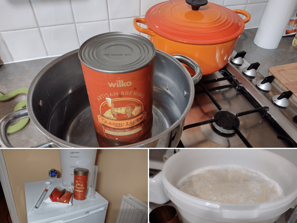
We used a Wilco Craft Lager brewing kit which produces 40 pints of beer. The kit contains a tin of concentrated malt, which you warm in a pan of water before adding it to about 3.5Lt of boiling water in the brewing bucket. Using cold water, add 1 kg of brewing sugar and top up the bucket to 43 Lt. Then, using a plastic spoon, make sure that the brew is thoroughly mixed and all the sugar dissolved. Finally, sprinkle the Lager yeast on top of the brew and place it in the fridge.
You then select the Fermenting option on the Beer Controller, keeping the brew at a constant temperature between 18 to 21 degrees.
After four days, open the Hop pack and sprinkle it onto the brew.
When fermentation stops after about ten days, bottle the beer and place the bottles back in the fridge. Now we need to reset the Beer Controller and choose the Finishing option. This will cool the beer down to between 15 to 18 degrees for another ten days.
After that, your beer should be ready to drink and enjoy!
Summary
Brewing great beer is all about temperature control, and different styles of beer require different fermentation and finishing temperatures. Our Beer Controller uses a modified fridge to keep your beer in the best possible environment to produce a great tasting brew.
Our first brew is in the making, and we’ll let you know how it’s progressing on social media.
Cheers!
Looking for more project inspiration? Discover our latest projects on the Project Hub.

Like what you read? Why not show your appreciation by giving some love.
From a quick tap to smashing that love button and show how much you enjoyed this project.

