Program the Arduino OPTA as a ModbusTCP PID Controller
Discover how you can program the Arduino Opta as a PID (Proportional, Integral, Derivative) controller communicating over ModbusTCP protocol and show how it integrates into our example Industrial Network.
Author: Peter Milne, engineer and Linux advocate with probably more SBCs than a Chandrayaan-3 moon lander.
Arduino’s collaboration with Finder to produce the Opta™ is a disruptive force in the PLC market place.
Opta is a PLC with 8 digital / analogue inputs and 4 isolated relay outputs rated at 10A and is powered at 12-24 VDC. Inside is a dual core STM32H747 MCU with an Arm Cortex® M7 running at 480 MHz and an M4 core running at 240 MHz.
A new Arduino PLC IDE supports all 5 languages of the IEC 61131-3 standard, and in addition to running PLC code, you can program Opta in C/C++ Arduino code to adapt the device to your own requirements. The IDE is free to use, and licensing is included in the product cost.
Opta targets Industrial IoT, Building Automation, Electrical loads management and Industrial automation and is available in 3 variants depending on communication requirements. Opta™ Lite has a 10/100BASE-T Port, Opta™ RS485 adds a half-duplex RS-485 serial interface, and Opta™ WiFi has an additional 802.11 b/g/n and Bluetooth® Low Energy transceiver.
In this project, we program Opta as a PID (Proportional, Integral, Derivative) controller communicating over ModbusTCP protocol and show how it integrates into our example Industrial Network.
We also provide a Python ModbusTCP client oven simulation to test out the controller. The PLC turns the oven on or off according to the temperature feedback loop sent over Modbus TCP.
The example shows how to use external Arduino libraries to add extra functionality as well as using the existing IEC 61131-3 PLC programming language facilities built into the Arduino PLC IDE.
It can be adapted to any process trying to achieve a stable setpoint, for example in building HVAC, oven and fridge control and industrial process automation.
Credit: l lefebvrene
Licence: MIT
Credit: Brett Beauregard
Licence: MIT
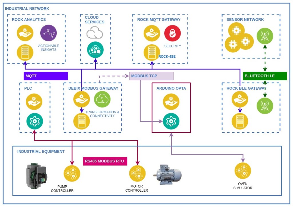
Step 1: Industrial Network
Arduino has published several example projects for Opta using Modbus RTU protocol so we will introduce Opta as a Modbus TCP Server into our existing industrial control network.
We focus on configuring Opta as a ModbusTCP Server and programming a PID controller using C/C++ integrated with the IEC 61131-3 PLC code. A Python client is used to remotely configure Opta and to act as an oven simulator that responds to the PLC outputs.
In this previous project, we demonstrated interfacing a PLC with Modbus RTU protocol via an MQTT gateway. The gateway code could be adapted to handle ModbusTCP commands in a similar way, so we don’t cover that aspect.
Step 2: Hardware
Opta has 8 digital (12-24VDC) / analogue (0-10V) software configurable inputs and 4 Normally Open (NO) 10A relays capable of actuating loads rated at 250 VAC and up to a maximum switching voltage of 400 VAC. It requires a 12-24VDC power supply.
We used the Opta WiFi version in our example, but any of the models will work as they all have Ethernet interfaces as standard, making them suitable for use with ModbusTCP protocol.
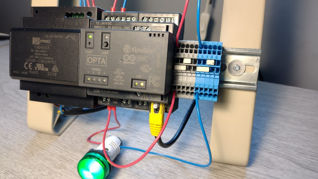
The circuit for this project is just a single LED connected to Output 1 of the Opta to show when the supply to the oven simulation is on or off. This could be connected to real equipment.
There are no electrical inputs to the PLC as the temperature feedback for the PID control is being sent via ModbusTCP. In other scenarios this could be received by a thermocouple connected to Opta’s 0 – 10V analogue inputs.
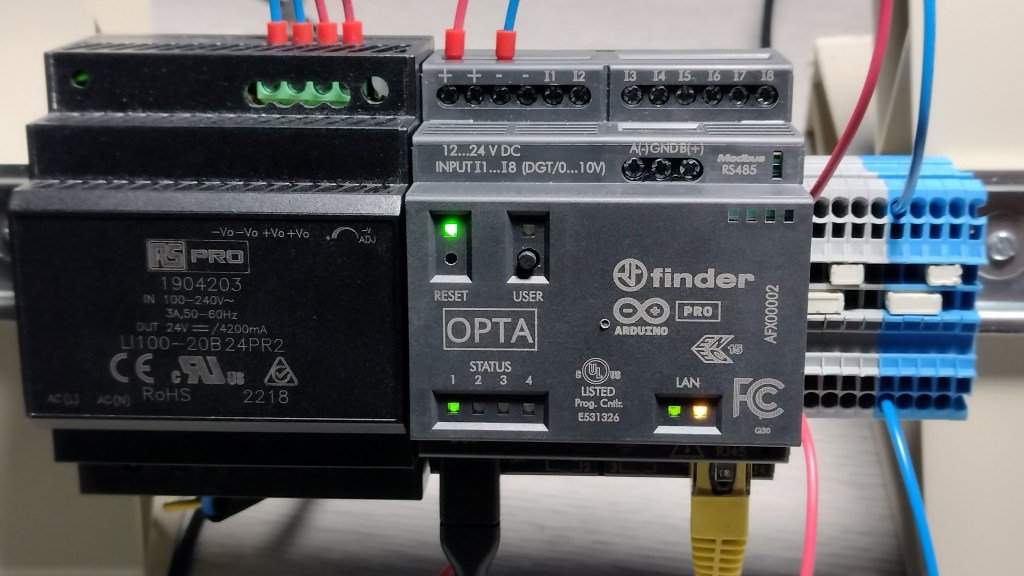
Power comes from a 24V / 4.2A DC power supply module mounted on DIN rail, shown to the LH side of the Opta in the image below. The device can be tested and flashed with just the USB-C 5V supply.
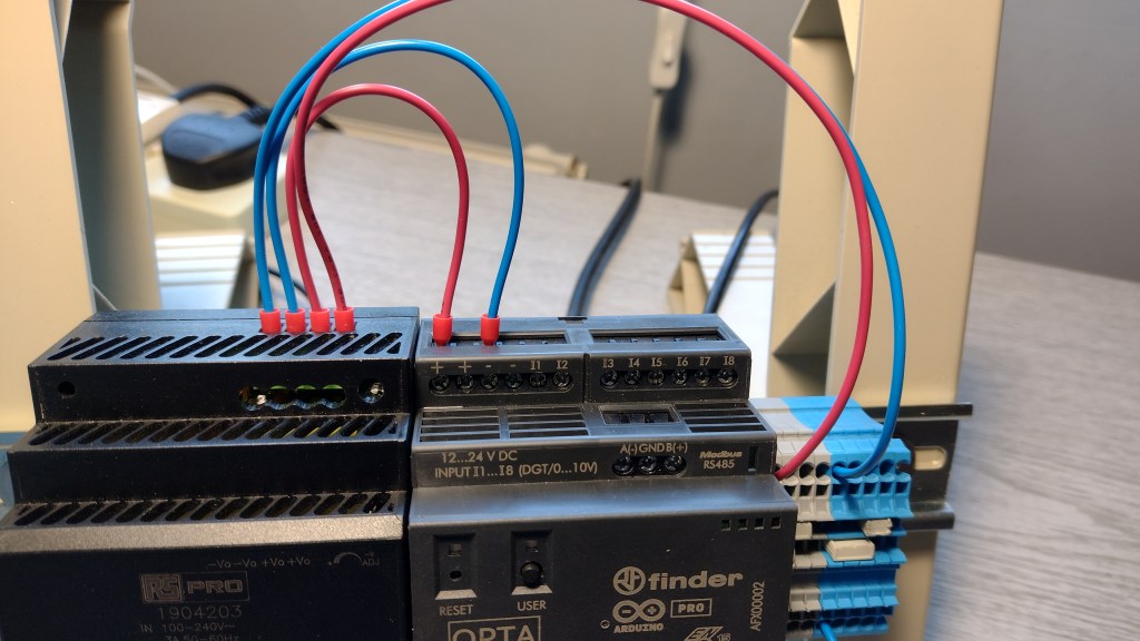
12 – 24V DC is required to trigger the relay outputs and power the device. We used the same supply to power the outputs in this project.
For the LED connection, the LH terminal of Output 1 is connected to the positive side of the power supply via the grey terminal block. The switched side of Output 1 is connected to the positive terminal on the LED. The negative LED terminal is connected to the negative side of the power supply via the blue terminal block.
Step 3: Arduino PLC IDE
2 options are available when it comes to the programming environments for Opta. The first is to use the standard Arduino IDE and program the device entirely in C/C++ with the aid of built-in library functions. There are examples on the Arduino site illustrating this approach.
For this project, we use the Arduino PLC IDE. This development environment supports the IEC IEC-61131-3 programming languages: Ladder Diagram (LD), Sequential Function Chart(SFC), Function Block Diagram (FBD), Structured Text (ST), Instruction List (IL), as well as Arduino sketches.
The PLC IDE is Windows 10 / 11 only software, so you will need an X86 host that runs this OS. The IDE is free to download and use, and the fine details of how to install it are covered on the Arduino PLC IDE downloads page, along with links to several examples.
Once you’ve installed the PLC IDE, you can access a detailed PDF manual for the IDE from the Help item in the Main menu.
Step 4: Opta Runtime
Before you can communicate with Opta using the PLC IDE you need to flash the device with the runtime code. This is a one-time process and only needs repeating if you repartition the memory (see the section on troubleshooting).
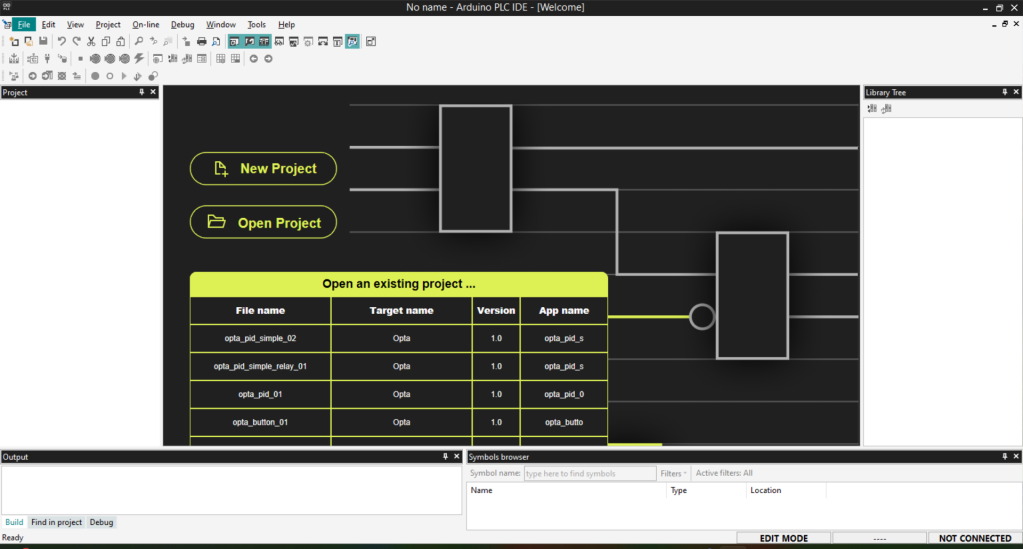
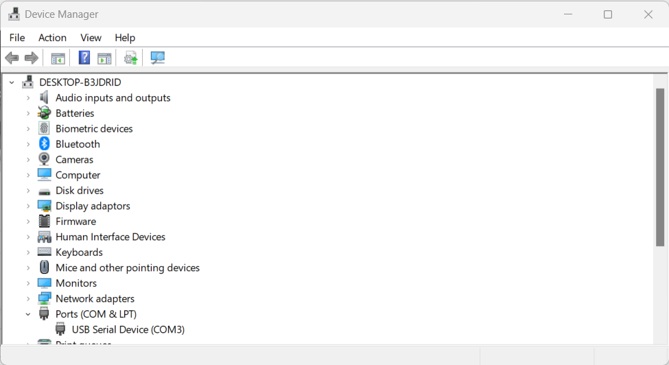
Connect Opta to your PC with a USB-C cable and open the PLC IDE. Choose to create a new project and make sure to set device type to Opta. If you look in the Windows Device Manager you should see a single COM port enumerated for the Opta (my system just has the Opta plugged in as COM3 – yours may be different).
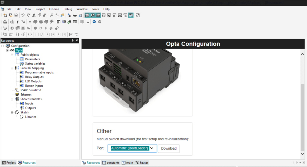
Now go to the Resources pane in the IDE, click the Opta item in the Configuration tree and scroll down to the Other box in the Configuration pane, then click the Download button. This should start to compile the runtime and end up by flashing it to the device.
Note: If you get a download error, double press the Reset button on the Opta.
Opta is in bootloader mode when the green LED above the reset button is blinking rapidly. Then try to download the code again.
Once the runtime has flashed successfully, disconnect the USB cable so the device powers off.
Step 5: Opta License
Before you can program OPTA using the PLC IDE, you need to register it and obtain a licence. The cost is included in the price of the device.
Reconnect the Opta to your PC using the USB cable and open the project created in the previous step. If you open the Windows Device Manager, you should now see 2 COM ports enumerated. In my case, this is COM3 & COM5.
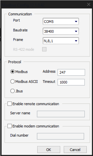
In the IDE menu bar click On-line and Setup Communication. In the DeviveLinkManager popup select the Modbus protocol.
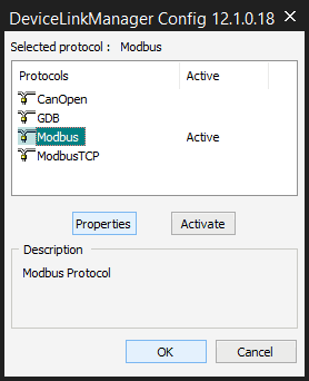
Now, click Properties, and set the Port to the HIGHEST of the two COM ports. Make sure that the Device Address is set to 247. Click OK to accept the options, returning to the Configuration pane.
This is how my Opta communication is configured:
Now, select On-line again, then Connect from the Main menu (or the Connect button in the Toolbar menu).
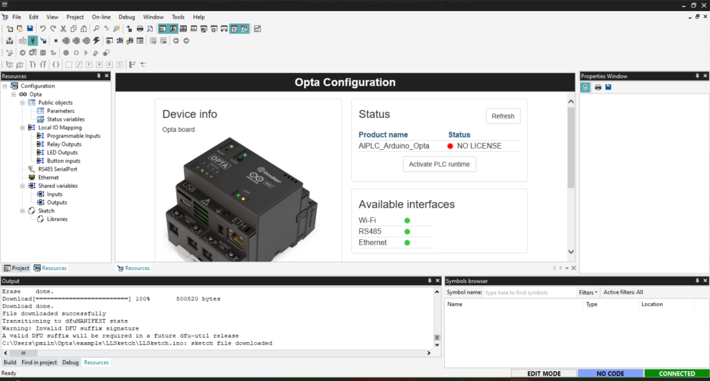
The Configuration pane should look something like this, depending on which variant you are using, showing there is NO LICENCE:
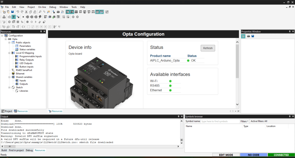
Click Activate PLC Runtime and then Refresh.
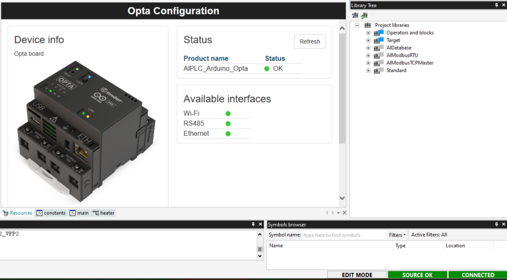
Your device should now be registered and show the green light in the Status box. Fortunately, you only need to do all of this once.
Step 6: Status Variables
In order to be able to exchange data between Opta and a ModbusTCP Client, we need to define Status Variables in the IDE. These are the Modbus Holding Registers we will use in the ModbusTCP commands.
Status Variables are added by selecting the node under Configuration -> Opta -> Public Objects in the Resources pane.
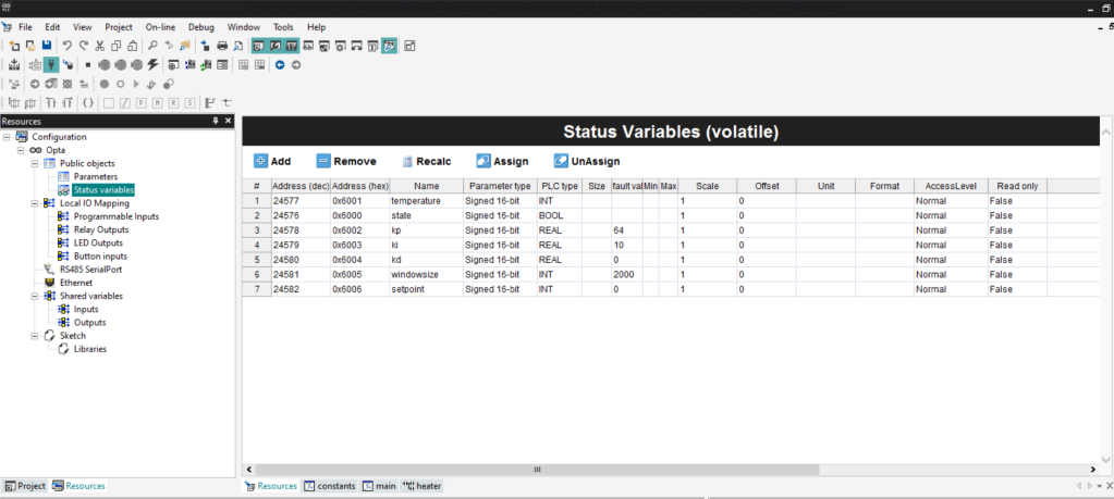
Click the Add button in the editor and add variables for each of the values that we want to interface. Set the PLC type accordingly and Read Only to FALSE so they can be updated.
I’ve added items for Temperature to hold the PID feedback temperature from our oven. State holds the On / Off state of the heater and all the other variables represent the PID constants that need setting for the algorithm.
Memory addresses are generated automatically and shown as Hex and Decimal values, which will be referred to the Modbus commands.
Note: default values only seem to work for INT variables and not REAL values.
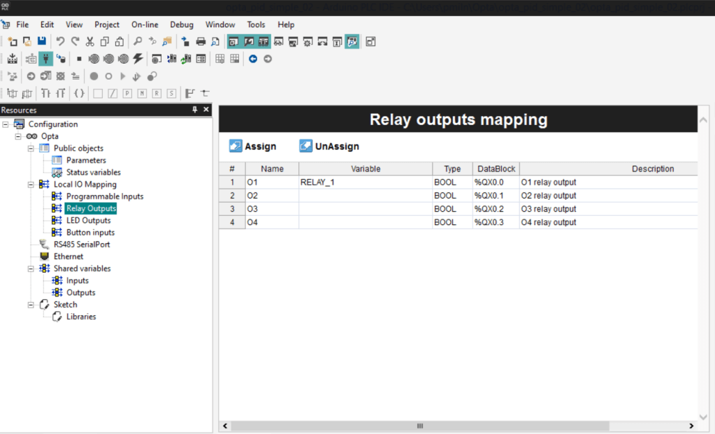
Step 7: IO Mapping
To reference the Opta IO hardware aliases need defining under the Local IO Mapping node for each type of IO in the Resources view. We will just be using the Relay Outputs and LED Outputs on the device.
Here we are adding an alias for the Relay O1, which is a BOOL type.
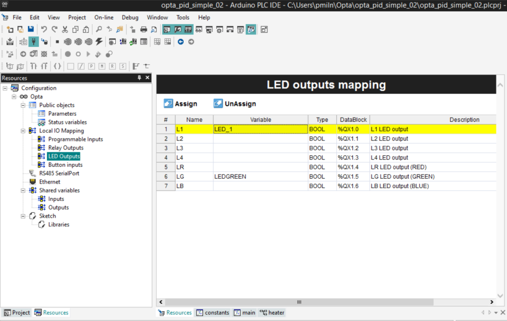
Set aliases for the L1 Status LED which we will program to turn on at the same time as Relay O1 and the LG LED which is the green LED above the RESET button. We will turn this on in the setup code to indicate that our code is up and running on the device.
Step 8: Shared Variables
Both Status Variables and Local IO Variables are only visible in the scope of the IEC modules termed Program Organization Units (POU’s) in the IDE.
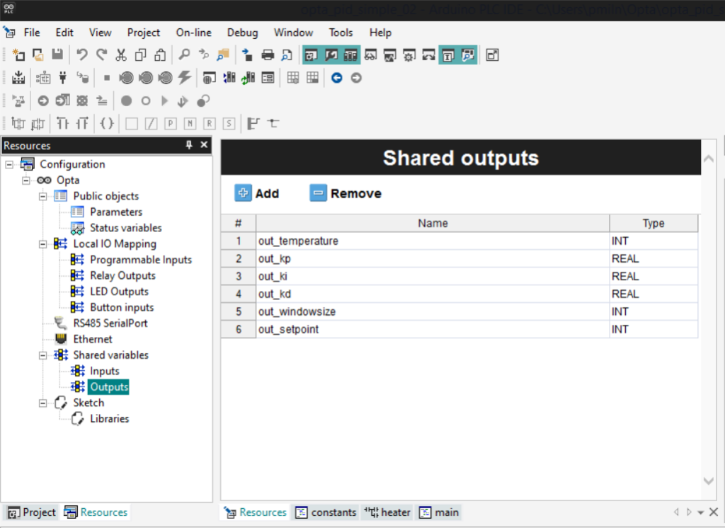
In order to pass values between POU’s and Arduino code we need to define Shared Variables, which are split into Inputs and Outputs.
Inputs pass values from the Arduino code to POU’s and Outputs pass values from POU’s to the Arduino sketch.
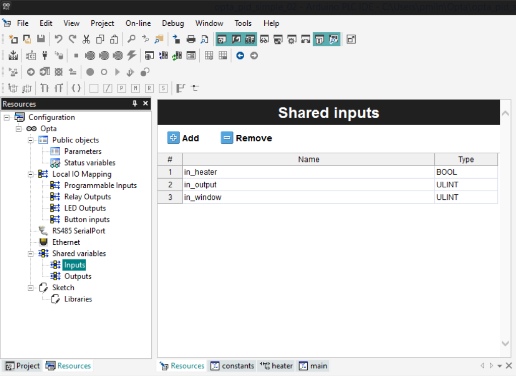
The in_heater variable contains the on/off status that is the result of the PID calculation and is used to switch Relay O1 on and off.
The in_output and in_window are used for debugging purposes to expose variables in the Arduino code to the IDE debugger.
Here are the Shared Inputs:
Both Status Variables and Local IO Variables are only visible in the scope of the IEC modules termed Program Organization Units (POU’s) in the IDE.
In order to pass values between POU’s and Arduino code we need to define Shared Variables, which are split into Inputs and Outputs.
Inputs pass values from the Arduino code to POU’s and Outputs pass values from POU’s to the Arduino sketch.
The in_heater variable contains the on/off status that is the result of the PID calculation and is used to switch Relay O1 on and off.
The in_output and in_window are used for debugging purposes to expose variables in the Arduino code to the IDE debugger.
Here are the Shared Inputs:
Step 9: POU’s
Program Organization Units (POU’s) are where Opta programs are defined using the IEC language facilities.
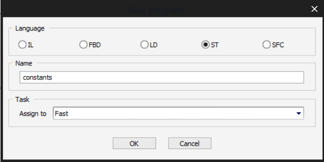
We are going to set up 3 separate POU’s using the different language options. To add a POU open the Project view and right click the top node and select New Program from the popup menu. Choose the Language option, give the program a Name and select the Task from the drop-down. The task determines how often the POU will run.
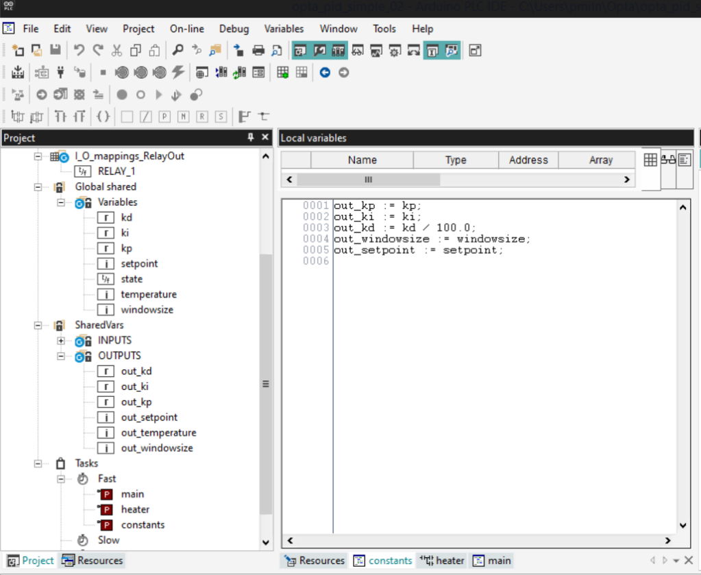
The first POU is named constants, which is a Structured Text unit that maps the Shared Variable PID constants and setpoint values to the Shared Output variables in the Arduino code. This runs as a Fast task which executes every 10 ms by default. It’s possible to change this at the Task level.
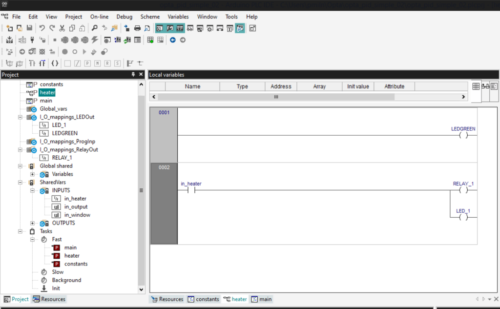
The next POU is a Ladder Diagram named heater and maps the in_heater Shared Variable in the Arduino code to Relay_1 and LED_1. They both become True when the PID output is True, turning on the heater.
This POU also runs every 10 ms as a Fast Task.
Variable nodes in the Project view can be dragged onto the LD editor Contacts and Coils to create the relationships.
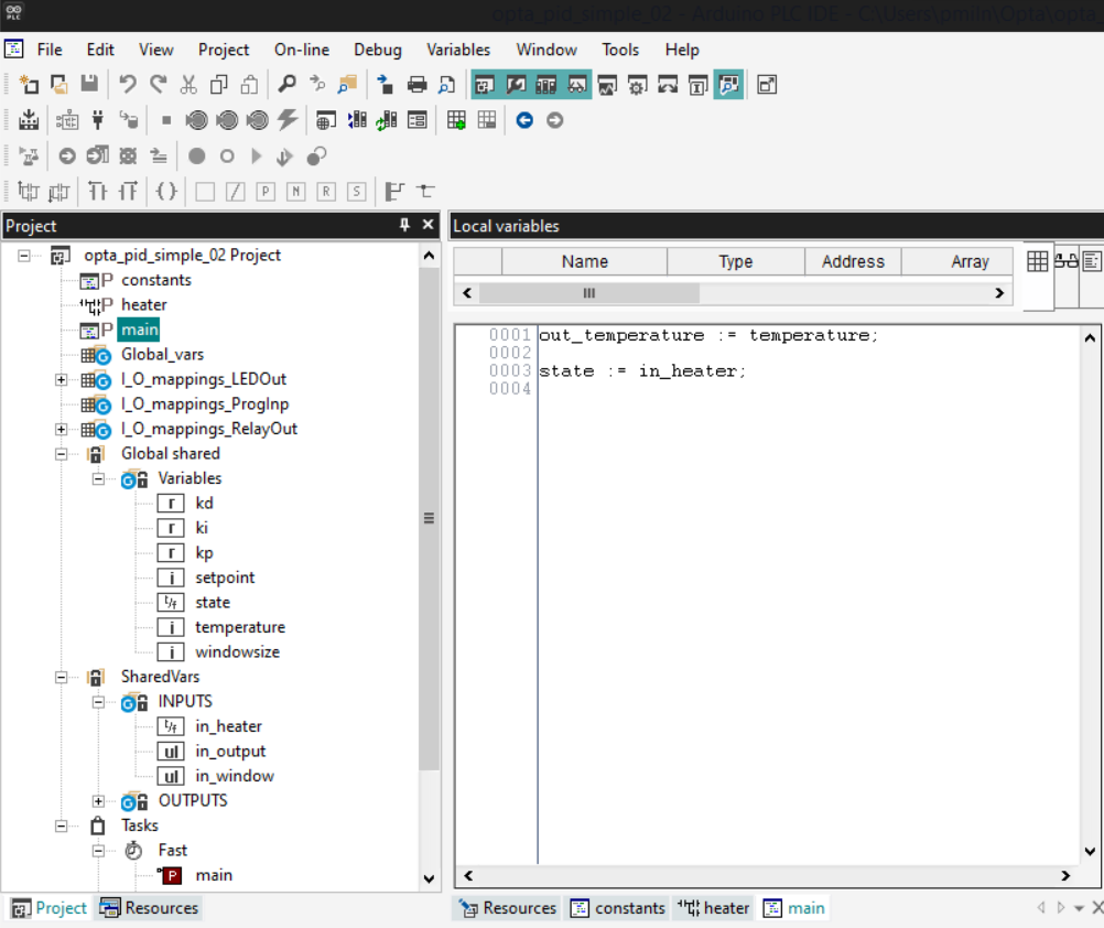
Finally, the main POU is an ST unit and is provided by default. The code synchronises the temperature received in the Status Variable with the Shared Variable in the Arduino module as an input to the PID calculation.
The temperature Status Variable is updated when the client sends a Write Holding Registers command, which we cover in the next steps.
It also synchronises the heater state Status Variable with the output from the PID calculation. The state variable is read by the Read Holding Registers command sent from the client.
Step 10: Modbus TCP
Opta is configured by default as a ModbusTCP Server with Unit ID: 255 in the Ethernet node of the Resources view but there are no options to configure a static IP address in the IDE.
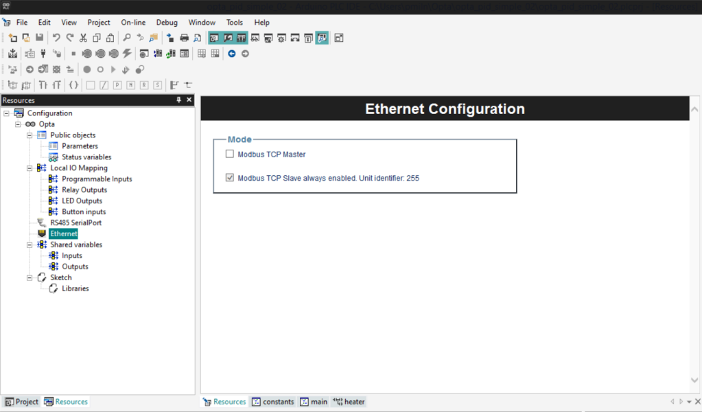
If you want to set a static IP address (which you almost certainly do), it’s necessary to add some Arduino Code using the editor by selecting the Arduino Sketch item of the Resources tree.
By default each new project contains the Ethernet setup code but the lines are commented out. Uncomment them and substitute suitable IP settings for your own network. Here’s mine:
#include <PortentaEthernet.h>
arduino::EthernetClass eth(&m_netInterface);

void setup()
{
	IPAddress ip(192, 168, 1, 40);
	IPAddress dns(192, 168, 1, 254);
	IPAddress gateway(192, 168, 1, 254);
	IPAddress subnet(255, 255, 255, 0);
	eth.begin(ip, dns, gateway, subnet);
}
Step 11: Arduino Libraries
A Library view in the IDE contains nodes for existing libraries bundled with the IDE, which are in a proprietary format. Currently there aren’t any additional libraries available, and there are no details as to how to write your own. Hopefully, this will come in future software releases.
There is, however, a way to add existing Arduino libraries for use with your own code.
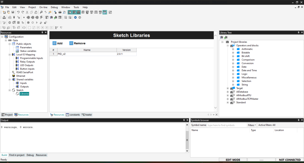
Clicking the Libraries node in the Resources pane opens an editor for adding existing Arduino libraries. These must be publicly available in the Arduino Libraries repository, and you just need to look up the library name and version number to add it into the table.
Over 6K libraries are currently available, and non-hardware-specific ones can be used with Opta. You can search for them from Arduino Libraries.
Here on GitHub, I’ve added the PID-v2 library, version 2.0.1 by Brett Beauregard for use with my PID controller.
Step 12: Arduino Code
The last programming step is to write the Arduino code to implement the PID controller. I adapted it from the PID library examples.
At the beginning, it includes the static IP address code for Ethernet along with the initialisation of the PID controller.
The main loop sets the PID control parameters and setpoint each time through the loop, which allows them to be changed on the fly to tune the controller and alter the setpoint using ModbusTCP commands from the client.
The window size calculation simplifies the PID maths. It sets a constant time window in which the PID algorithm determines whether to change the relay state, which is done in the if / else statements at the end.
Note that Input / Output Shared Variables are referenced using PLCIn.variable_name / PLCOut.variable_name object attributes.
#include <PortentaEthernet.h>
#include "PID_v2.h"
arduino::EthernetClass eth(&m_netInterface);
double Kp = 2, Ki = 5, Kd = 1;
PID_v2 myPID(Kp, Ki, Kd, PID::Reverse);
unsigned long windowStartTime;

void setup() {
	IPAddress ip(192, 168, 1, 40);
	IPAddress dns(192, 168, 1, 254);
	IPAddress gateway(192, 168, 1, 254);
	IPAddress subnet(255, 255, 255, 0);
	eth.begin(ip, dns, gateway, subnet);
    delay(5000);
    windowStartTime = millis();
    myPID.SetOutputLimits(0, 5000);
    myPID.Start(PLCOut.out_temperature, 0, 100);
}

void loop()
{
    const double input = PLCOut.out_temperature;
    const double Kp = PLCOut.out_kp;
    const double Ki = PLCOut.out_ki;
    const double Kd = PLCOut.out_kd;
    const int WindowSize = PLCOut.out_windowsize;
    const double setpoint = PLCOut.out_setpoint;

    myPID.SetOutputLimits(0, WindowSize);
    myPID.Setpoint(setpoint);
    myPID.SetTunings(Kp, Ki, Kd);
    const double output = myPID.Run(input);
    PLCIn.in_output = output;

    while (millis() - windowStartTime > WindowSize) {
        windowStartTime += WindowSize;
    }
    unsigned long window = millis() - windowStartTime;
    PLCIn.in_window = window;
    if (output < window)
        PLCIn.in_heater = true;
    else
        PLCIn.in_heater = false;
}
The full code listing is available on GitHub.
Step 13: Flashing
Now that all the coding is complete, it is time to flash it to the Opta. To transfer Arduino code communication needs to be via the serial interface using the USB connection.
Make sure Opta is connected with the USB cable and the DeviceLinkManagers is set to Modbus then select Connect. Connection status is visible in the bottom RH side of the Status Bar. This should be Green and display CONNECTED.
Now, select the Compile option from the Project menu and click the Compile icon in the Toolbar. Compilation should take place, and the output should be displayed in the Output view, including any errors which need fixing.
Assuming everything compiled OK, select the Download from the On-line menu option or click the Download icon in the Toolbar. Accept any pop-ups requesting a restart. You will have to re-connect if the system performs a cold restart.
If everything was successful, Opta’s green RESET LED should be on and both the LAN LEDs should be illuminated. In the IDE status bar, you should see SOURCE OK and CONNECTED.
Once Opta is in this state, if you need the debugging facilities of the IDE, keep it connected to your host. Otherwise, you can disconnect the USB cable and power the device with the external power, and it will run freestanding.
Step 14: ModbusTCP Configuration Client
We need to send the PID configuration parameters to the Opta server over ModbusTCP to set the PID constants and the temperature Setpoint.
There are several great Modbus TCP modules available in Python, and I’ve chosen to use pyModbusTCP for the clients.
I installed it into a virtual environment on my Linux host like this:
$ cd python/opta-pid
$ python -m venv venv
$ source venv/bin/activate
(venv) $ pip install pyModbusTCP
I created a Python script to set the PID parameters. It instantiates a ModbusTCP client with the Opta’s IP address and ID, sets values for the PID constants and setpoint, puts them into a list and sends them to the Opta in the Modbus write command.
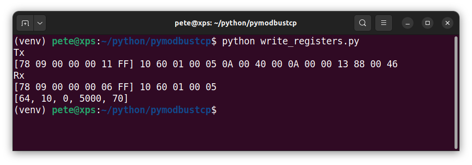
The write command takes 2 arguments: the start address for the first register and a list of values. To obtain the address, subtract 1 from the decimal address of the Kp Status Variable in Step 7.
Here’s the Python code. Note that the Kd constant is scaled as we can only send integer values:
"""Write multiple registers"""
from pyModbusTCP.client import ModbusClient

c = ModbusClient(host='192.168.1.40', port=502, unit_id=255, debug=True, auto_open=True)

Kp = 64
Ki = 10
Kd = int(0 * 100)  # Scale to int
window_size = 5000
setpoint = 100
constants = [Kp, Ki, Kd, window_size, setpoint]
c.write_multiple_registers(24577, constants)
print(constants)
Send the config settings over ModbusTCP with:
(venv) $ python write_registers.pyWith debug set to True in the client, the terminal output shows the Modbus commands being sent and received (in Hex) and a summary of the values in the list.
You can check the values have been configured correctly by dragging the Shared Output variables into the Watch view in the IDE:

Step 15: Python Simulator Client
To make testing the PID controller easier I’ve written a simple ModbusTCP client that simulates a plant that heats up and cools down as it’s switched on and off.
The main plant class instantiates a couple of temperature profiles which run in their own threads. One heats up and the other cools down according to the rate determined in their constructors:
"""Model temperature profile that changes at a constant rate"""
from time import sleep
from threading import Thread
from threading import Lock
from threading import Event
from pyModbusTCP.client import ModbusClient

class TemperatureProfile(Thread):
    """Sets a fixed amount by which the temperature is incremented or decremented per second."""
    temperature = 90  # Class instance

    def __init__(self, identity, lock, event, dtemp, dtime):
        """Sets the rate of change for the temperature.
        dtemp = number of degrees change each cycle
        dtime = number of seconds between temperature changes"""
        Thread.__init__(self)
        self.dtemp = dtemp
        self.dtime = dtime
        self.identity = identity
        self.lock = lock
        self.event = event

    def run(self):
        """Updates the class temperature instance from within its own thread"""
        while True:
            if TemperatureProfile.temperature is not None:
                self.event.wait()
                with self.lock:  # Acquire the lock
                    TemperatureProfile.temperature = TemperatureProfile.temperature + self.dtemp
                    sleep(self.dtime)
The main thread of the simulator runs each second in a loop and sends a Modbus command to get the heater state from the Opta, the result of which switches the simulator’s heater thread on or off accordingly. If the heating thread is on, the cooling thread is suspended and vice versa.
At the end of the loop a second Modbus command is sent to transfer the latest temperature reading from the simulator to the Opta which is used in the next PID calculation.
Both the current temperature and setpoint for the simulator are logged to a file so the results can be graphed to aid tuning the PID controller parameters.
We can only send integer temperature values between 0 and 65535, so there’s a small function to convert negative temperatures into a two’s complement value. These get converted automatically back to negative integers by the Opta runtime.
Here’s the main client listing:
"""Modbus TCP Plant Temperature Simulator client"""
import logging
import time
from temperature_profile import TemperatureProfile
from time import sleep
from threading import Lock
from threading import Event
from pyModbusTCP.client import ModbusClient
from enum import Enum
logging.basicConfig(filename='output.log', format='%(asctime)s %(message)s', datefmt='%I:%M:%S', encoding='utf-8', level=logging.DEBUG)
class State(Enum):
COOLING = 0
HEATING = 1
def tows(integer_16: int) -> int:
if integer_16 is not None:
return int(bin(integer_16 % (1 << 16)), 2)
else:
return 0
class PlantTemperatureSimulator():
shared_lock = Lock()
heating_event = Event()
cooling_event = Event()
heating_profile = TemperatureProfile('Heating', shared_lock, heating_event, 1, 2)
cooling_profile = TemperatureProfile('Cooling', shared_lock, cooling_event, -1, 2)
c = ModbusClient(host='192.168.1.40', port=502, unit_id=255, debug=False, auto_open=True)
def __init__(self):
previous_state = State.COOLING.value # Set initial state
PlantTemperatureSimulator.heating_profile.start()
PlantTemperatureSimulator.cooling_profile.start()
while True:
try:
register = PlantTemperatureSimulator.c.read_holding_registers(24575, 7)
current_state = register[0]
setpoint = register[6]
if previous_state != current_state:
# State has changed
if current_state == State.HEATING.value:
PlantTemperatureSimulator.cooling_event.clear()
PlantTemperatureSimulator.heating_event.set()
print(f'Heating...')
else:
PlantTemperatureSimulator.heating_event.clear()
PlantTemperatureSimulator.cooling_event.set()
print(f'Cooling...')
previous_state = current_state
except:
print("Oops! ModbusTCP Error, trying again...")
try:
# Send a two's complement value as int in range 0 - 65535
PlantTemperatureSimulator.c.write_single_register(24576, tows(TemperatureProfile.temperature))
except:
print("Oops! ModbusTCP Error, trying again...")
logging.info("%s %s", TemperatureProfile.temperature, setpoint)
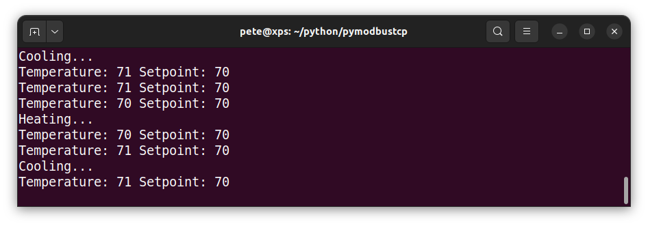
print(f'Temperature: {TemperatureProfile.temperature} Setpoint: {setpoint}')
sleep(1)
if __name__ == '__main__':
PlantTemperatureSimulator()
The output is shown in the terminal as well as logged in the file output.log.
Step 16: Testing
To run a test, power the Opta on and initialise the PID controller by running the configuration client, then start the plant simulator client. After a few minutes, if the PID controller is set correctly the temperature should converge to the setpoint and remain quite close to it after a few minutes.
If you want to change the PID constants or setpoint, send another configuration command with the client.
There are various methods to tune the PID constants. Start by setting the time window to 5000 ms and set Ki & Kd to zero. Set Kp and keep doubling it until it diverges from the setpoint, then halve the value until it oscillates around it.
Now, add in a small Ki constant in a similar way, until the readings converge on the setpoint. I left Kd at zero for this simulator.
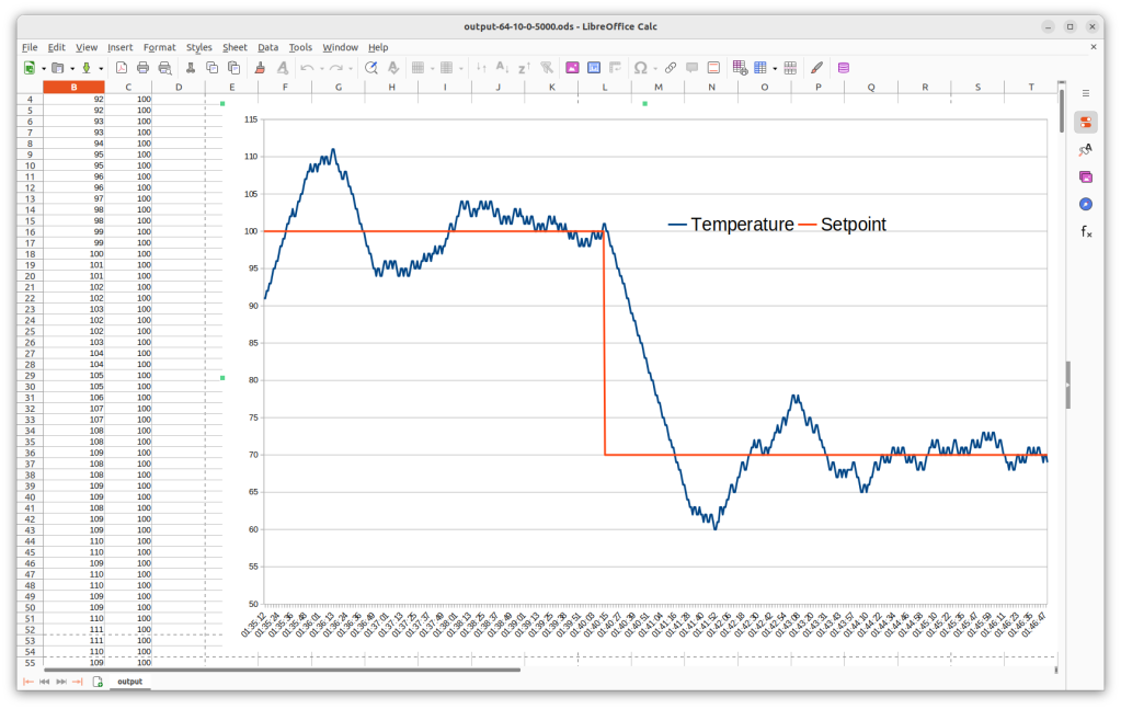
Here’s a graph of the output.log for setpoints of 100 and 70 degrees with Kp = 64, Ki = 10, Kd = 0 Window Size = 5000 with a heating / cooling rate of 1 degree per second.
I managed to get an accuracy of about +/- 1% after a bit of experimentation with the settings.
Step 17: Troubleshooting
If you are having issues with serial communication in the IDE, check that you are using the correct COM port and that the LinkDeviceManager is set to Modbus with a baud rate of 38400 and Modbus address 247.
You can only flash Arduino code changes when connected via serial.
For POU changes only and debugging, it’s possible to use the IDE over a ModbusTCP connection with the correct Modbus Server IP setting in the LinkDeviceManager.
Try double-clicking the RESET button to put Opta into bootloader mode with the green LED blinking rapidly.
If this doesn’t work, you can re-partition the memory in the Opta by flashing this sketch using the Arduino IDE. Make sure you are connected using the lowest COM port setting. When the sketch has loaded, open the serial monitor and wait until the output informs that it is safe to disconnect the device.
You can repartition the Opta’s memory by following this tutorial.
There is an Opta category in the Arduino Forum with useful information and you can also post there to get help from the wonderful Arduino contributors.
Summary
Opta is an exciting development in the PLC device space and opens up all number of possibilities to adapt the PLC for specific requirements, at a reasonable cost.
In this project, we customised the Opta as a ModbusTCP server in our Industrial Network and showed how to implement a PID controller using an existing Arduino library, in conjunction with IEC 61131-3 language modules available in the Arduino PLC IDE.
I found the learning curve a bit steep but once you get used to the quirks, you realise what a great product this is and start to envisage its possible applications.
There are a growing number of example projects and tutorials available linked from the Opta product page. There’s high-quality documentation of the PLC IDE from within the Windows-only app and an active and responsive Arduino Forum to help you out when you need it.
References
![]()

Let’s invent the future together
What’s your challenge? From augmented reality to machine learning and automation, send us your questions, problems or ideas… We have the solution to help you design the world. Get in touch today.
![]()
Looking for something else? Discover our Blogs, Getting Started Guides and Projects for more inspiration!
Like what you read? Why not show your appreciation by giving some love.
From a quick tap to smashing that love button and show how much you enjoyed this project.

