The Raspberry Pi has a 40-pin GPIO (general-purpose input/output) header. You can use the pins to interface with external components, allowing you to control motors, sensors and LED’s.
1. Get your Pi ready
2. Know your pins
There are several types of pin as described below. Strictly speaking, only the yellow pins shown below are GPIO (general purpose in/out). They are identified by a number, which as you can see below, is NOT sequential.
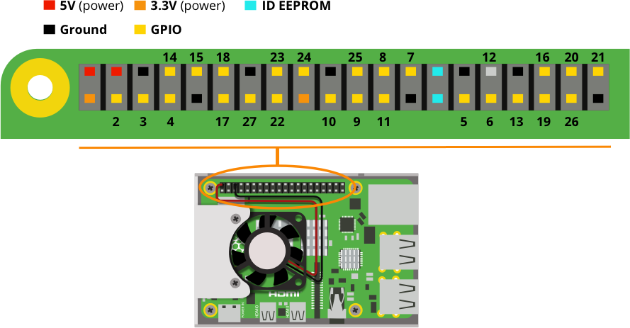
Voltages
There are two 5V pins (red) and two 3.3V pins (orange) on the board, as well as 8 ground pins (0V), which are unconfigurable. There’s also 25 general purpose 3.3V pins (yellow), meaning outputs are set to 3.3V and inputs are 3.3V-tolerant.
Outputs
A GPIO pin designated as an output pin can be set to high (3.3V) or low (0V). You define this using code.
Inputs
A GPIO pin designated as an input pin can be read as high (3.3V) or low (0V). This is made easier with the use of internal pull-up or pull-down resistors. Pins GPIO2 and GPIO3 have fixed pull-up resistors, but for other pins this can be configured using code.
Functions
Besides simple input and output devices, the GPIO pins can also be used with other functions, some are available on all pins, others on specific pins.
PWM (pulse-width modulation)
Software PWM available on all pins
Hardware PWM available on GPIO12, GPIO13, GPIO18, GPIO19
SPI
SPI0: MOSI (GPIO10); MISO (GPIO9); SCLK (GPIO11); CE0 (GPIO8), CE1 (GPIO7)
SPI1: MOSI (GPIO20); MISO (GPIO19); SCLK (GPIO21); CE0 (GPIO18); CE1 (GPIO17); CE2 (GPIO16)
I2C
Data: (GPIO2); Clock (GPIO3)
EEPROM Data: (GPIO0); EEPROM Clock (GPIO1)
Serial
TX (GPIO14); RX (GPIO15)
While connecting up simple components to the GPIO pins is perfectly safe, it’s important to be careful how you wire things up.
LEDs must have resistors to limit the current passing through them to avoid damage.
Do not use 5V for 3V3 components.
Do not connect motors directly to the GPIO pins, use an H-bridge circuit or a motor controller board.
Clip-on pin header labels are available although they won’t fit if your Pi has a case, you can also print a Raspberry Leaf which you can find here.
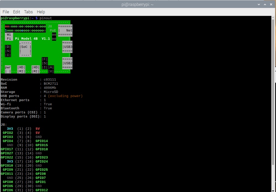
You can view the GPIO reference shown below on your Raspberry Pi by opening a terminal window and running the following command:
pinout
For a more in depth GPIO reference you can refer to this interactive guide.
3. Programming with GPIO
You can control GPIO pins using a number of programming languages and tools. Some popular ones are:
GPIO with Scratch 1.4
GPIO with Scratch 2
GPIO with Python
GPIO with C/C++ using standard kernel interface via libgpiod
GPIO with C/C++ using 3rd party library pigio
GPIO with Processing 3
A good place to get started is this project.
Like what you read? Why not show your appreciation by giving some love.
From a quick tap to smashing that love button and show how much you enjoyed this project.

