In this project, you’ll be introduced to using the GPIO pins of your Raspberry Pi and how to integrate them with electronic components using Python.
1. Get your Pi ready
- You should start with a switched-on Raspberry Pi connected to mouse, keyboard and monitor, you can learn here how to do it using an Okdo Pi kit
2. Build the circuit
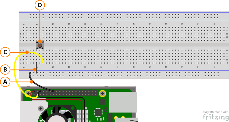
- Connect a female-male jumper A from the 7th pin on the top row of the Pi to the first patch point on the ground (blue rail) of the breadboard
- Connect a male-male jumper B from the 3rd pin on the ground (blue rail) of the breadboard to patch point A5 on the breadboard
- Connect female-male jumper C from the 2nd pin on the bottom row of the Pi to A7 on the breadboard
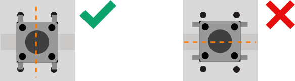
- Connect the switch D across the valley of the breadboard so that 1 pin is in F5 and another in E5
The switch pins should easily fit into the patch points of the breadboard, if they don’t, the switch is not being positioned correctly.
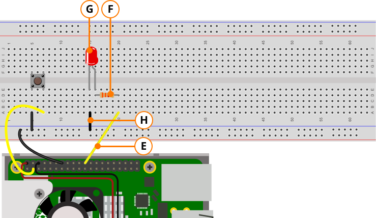
- Connect jumper E from the 11th pin on the top row of the Pi to A11
- Connect the resistor F from D16 to D20 on the breadboard
- Connect the positive (longer leg) of the LED to E15 and the negative (shorter leg) to E16
- Connect jumper H from A15 to the ground (blue rail) of the breadboard
3. Programme the Pi

- Navigate to the Raspberry icon on the top left of your Raspberry Pi’s desktop and open “Thonny Python IDE” from the “Programming“ menu
from gpiozero import LED
from time import sleep
from gpiozero import Button
button = Button(2)
led = LED(25)
while True:
    button.wait_for_press()
    led.on()
    led.off()
- Paste the code above into Thonnny’s editor window
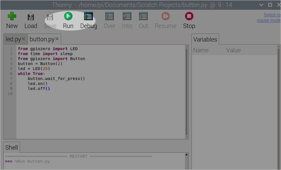
- Click Run on Thonny
Your LED should now be cycling through on and off when you press the switch
Like what you read? Why not show your appreciation by giving some love.
From a quick tap to smashing that love button and show how much you enjoyed this project.

