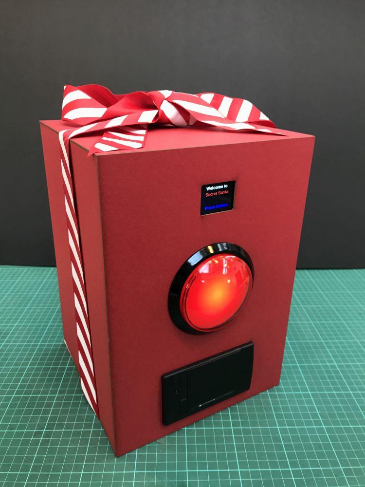
If it all works, why not tie a ribbon around it!
Fancy over complicating a simple task in order to try out some nice bits of Arduino kit this Christmas? If so, then this Secret Santa Machine is the project for you.
It does what it says on the tin and using a full colour TFT screen, it invites by name each person on the list to press the giant red button.It then prints them a ticket with their secret Santa person on using a thermal printer module.
It uses an Arduino, the Adafruit ST7735 1.8” colour display and the thermal printer module from Cool Components.
Resources
Arduino Code
Adafruit TFT display
-
- Adafruit Learn page for 1.8” TFT breakout
- ST7735 datasheet
- JD-T1800 display datasheet
- Arduino libraries and examples(although easier to use the built in library manager)
Thermal Printer
Power Supply
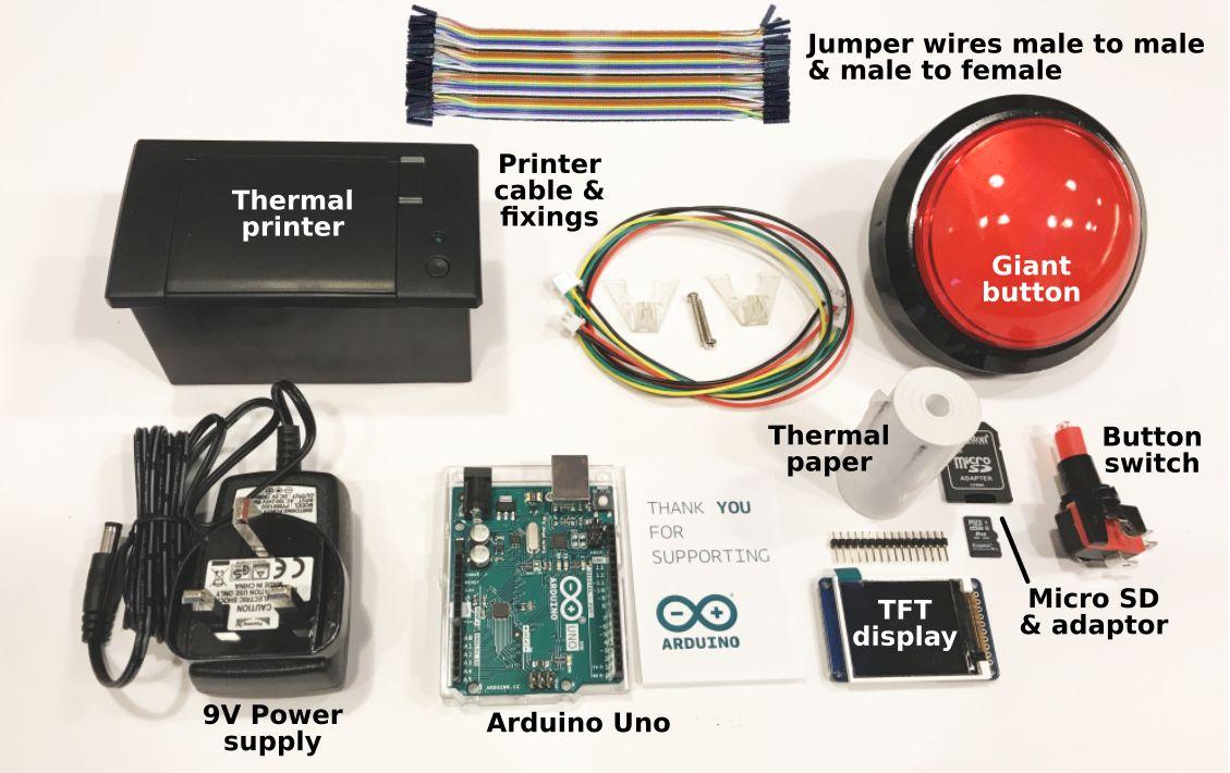
Bill of Materials (BOM)
Step 1
Download and install the latest version of Arduino IDE (IDE = Integrated Development Environment) on your computer from Arduino.cc
Step 2
Add the library for the TFT display to the Arduino IDE; open Arduino, navigate to Sketch > Include Library > Manage Libraries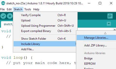
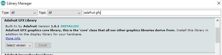
In the Library Manager search bar, type Adafruit ST7735. When the library for it appears,click install.
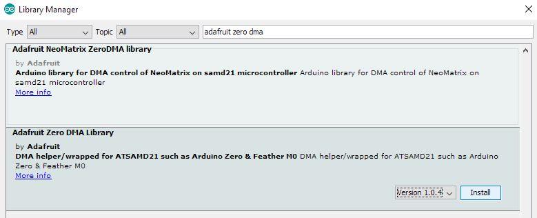
Now do the same for the Adafruit GFX and Adafruit Zero DMA libraries as shown here.
Finally restart the Arduino IDE so the libraries are correctly loaded.
Step 3
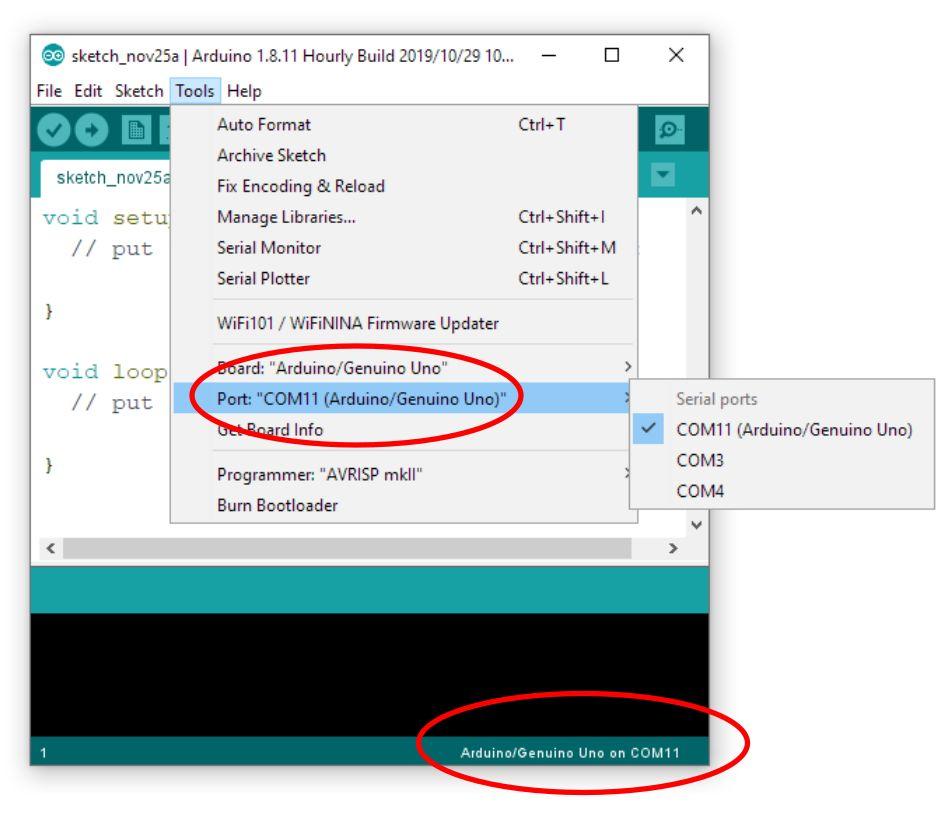
Download the Secret Santa Machine Arduino code from the Github page and open it in your Arduino IDE.Now plug your bare Arduino into your computer with the USB lead and confirm the Arduino IDE can find your Arduino board OK like this:
Step 4
We are now ready to take a look at the hardware.We will start with the TFT display. The Adafruit page gives pin out details for the display as follows:
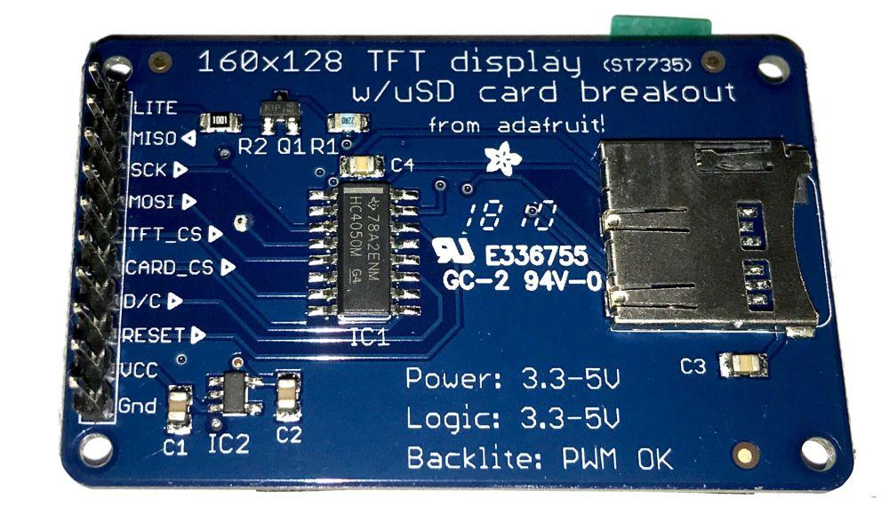
- Lite-this is the PWM input for the back light control. Connect to 3-5VDC to turn on the back light. Connect to ground to turn it off. Or, you can PWM at any frequency.
- MISO-this is the SPI Master In Slave Out pin, its used for the SD card. It isn’t used for the TFT display which is write-only
- SCK-this is the SPI clock input pin
- MOSI-this is the SPI Master Out Slave In pin, it is used to send data from the micro controller to the SD card and/or TFT
- TFT_CS-this is the TFT SPI chip select pin
- Card_CS-this is the SD card chip select, used if you want to read from the SD card.
- D/C-this is the TFT SPI data or command selector pin
- RST-this is the TFT reset pin. Connect to ground to reset the TFT! Its best to have this pin controlled by the library so the display is reset cleanly, but you can also connect it to the Arduino Reset pin, which works for most cases.
- Vcc-this is the power pin, connect to 3-5VDC-it has reverse polarity protection but tryto wire it right!
- GND-this is the power and signal ground pin.
The first step is to cut the strip of header pins to the correct number to fit the board and then solder them onto the TFT display. Make sure you put the short legs up through the circuit board from underneath, leaving the long legs ready to plug into the breadboard when soldering is finished. You only need to solder them on the top side like this:
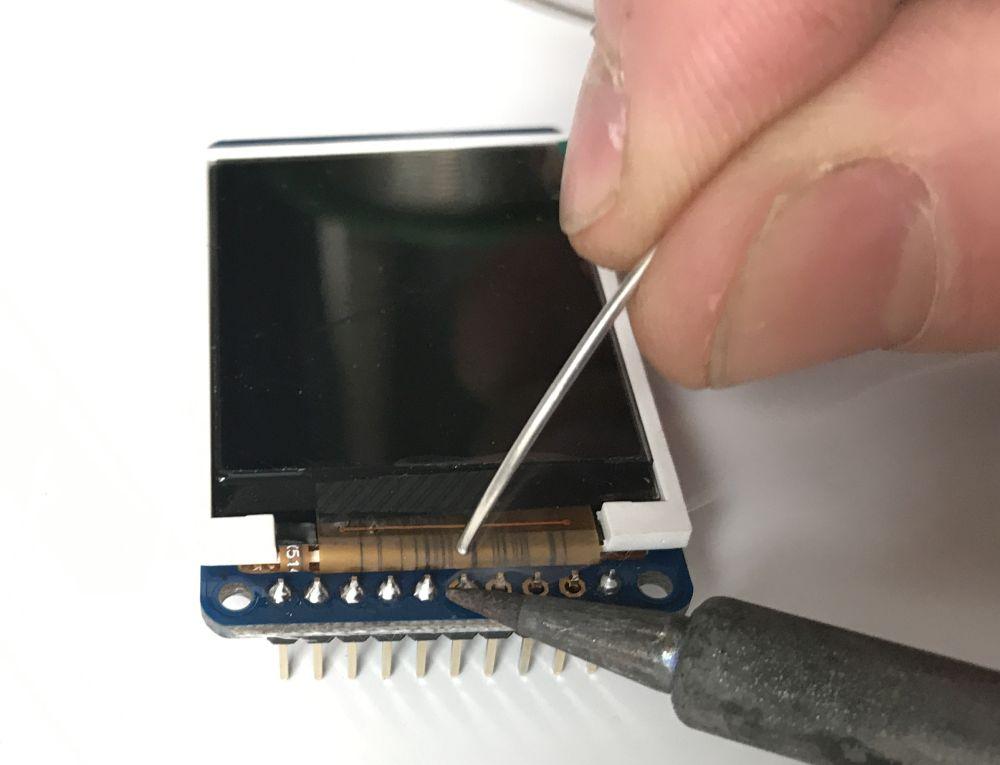
Follow the great Adafruit breakout assembly guide for this. When you are finished, click through to their next page on wiring and test.
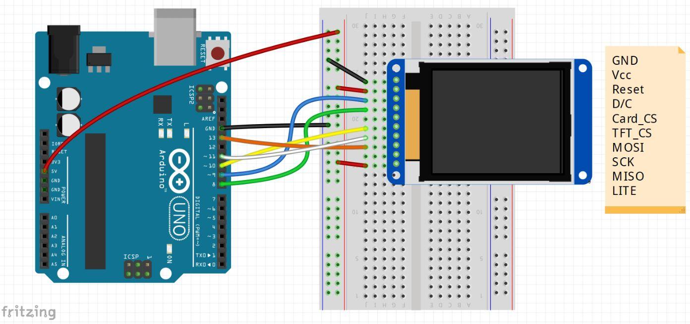
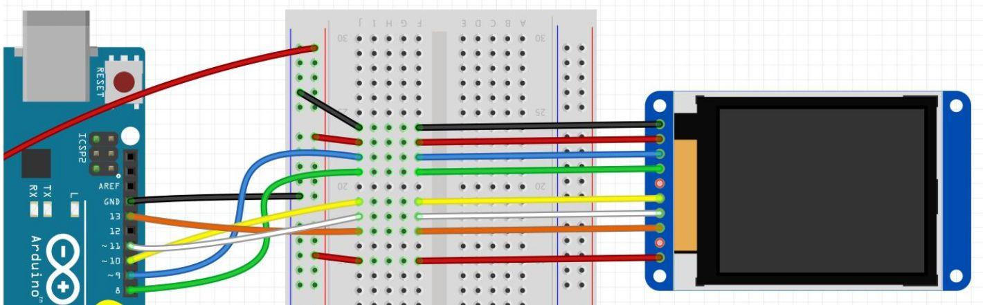
We are now going to use the dedicated SPI pins on Arduino to interface with the display. You can connect it in a different way using other pins, but communication will be much slower.
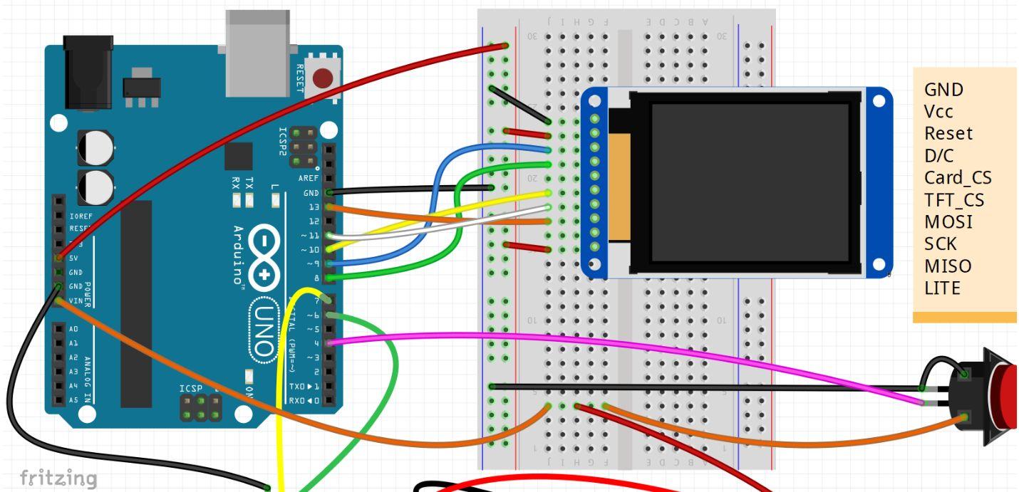
- GND connects to Arduino ground-Black wires.
- Vcc3-5V Vin connects to the Arduino 5V pin-Red wire.
- Reset connects to our TFT reset pin. We are using Digital pin 9 but you can change this pin in the code-blue wire.
- D/C connects to our SPI data/command select pin. We’ll be using Digital pin 8, but you can change this pin too-green wire.
- Card_CS
- TFT_CS connects to our SPI Chip Select pin. We are using Digital pin 10 but you can change this to any pin in the code. Yellow wire.
- MOSI connects to SPI MOSI. On Arduino Uno it is Digital pin 11. White wire.
- SCK connects to SPI clock which is Arduino Uno Digital pin 13.Orange wire.
- LITE connects to 5V to illuminate the display back light.
Step 5
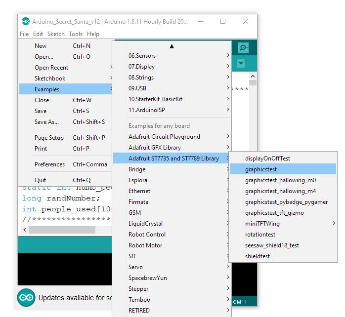
In the Arduino IDE go to Examples > Adafruit ST7735 > graphics test and run the example code to test the display works.
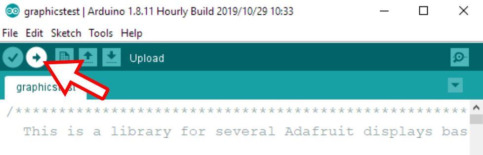
In case you are new to Arduino, you click on the Upload icon to upload the code to your Arduino board.
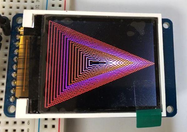
I fall goes to plan, you should get a series of graphics and text displayed. If nothing happens,make sure you have the ‘LITE’ pin hooked up to 5V correctly to power the back light.
As an optional extra if you would like to display bitmaps on the screen, you need a micro SD card and can follow the excellent Adafruit tutorial.
Step 6
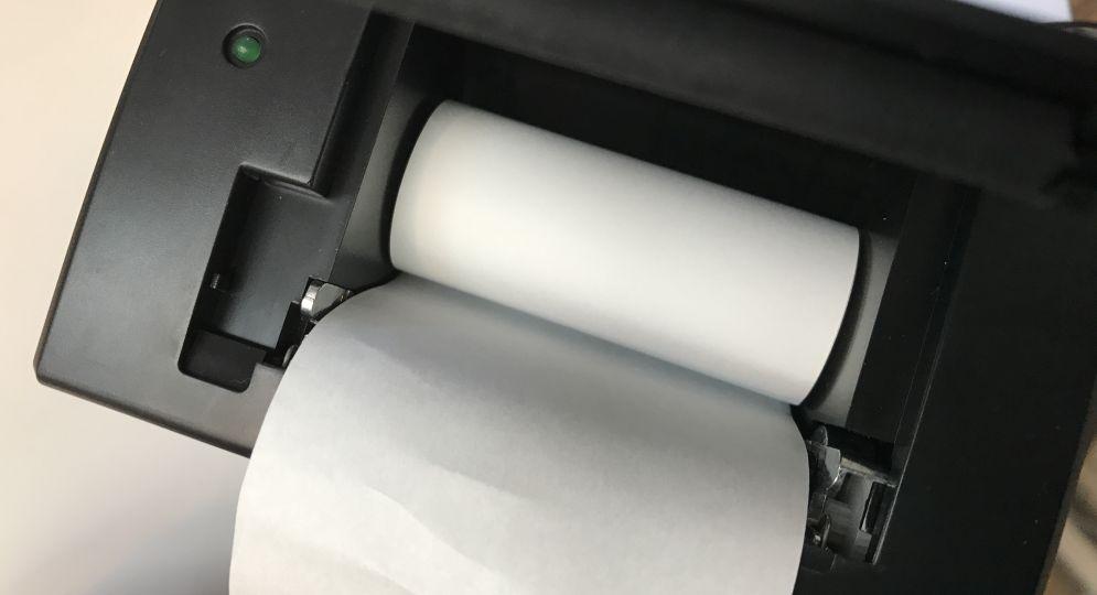
Now it is time to look at the thermal printer.Load the thermal paper roll into the printer and close the door with some paper protruding past the cover.Make sure the thermal side of the paper is facing down onto the print head. You can test it by scraping your thumbnail across a piece of the paper and the heat from friction will leave a dark mark.
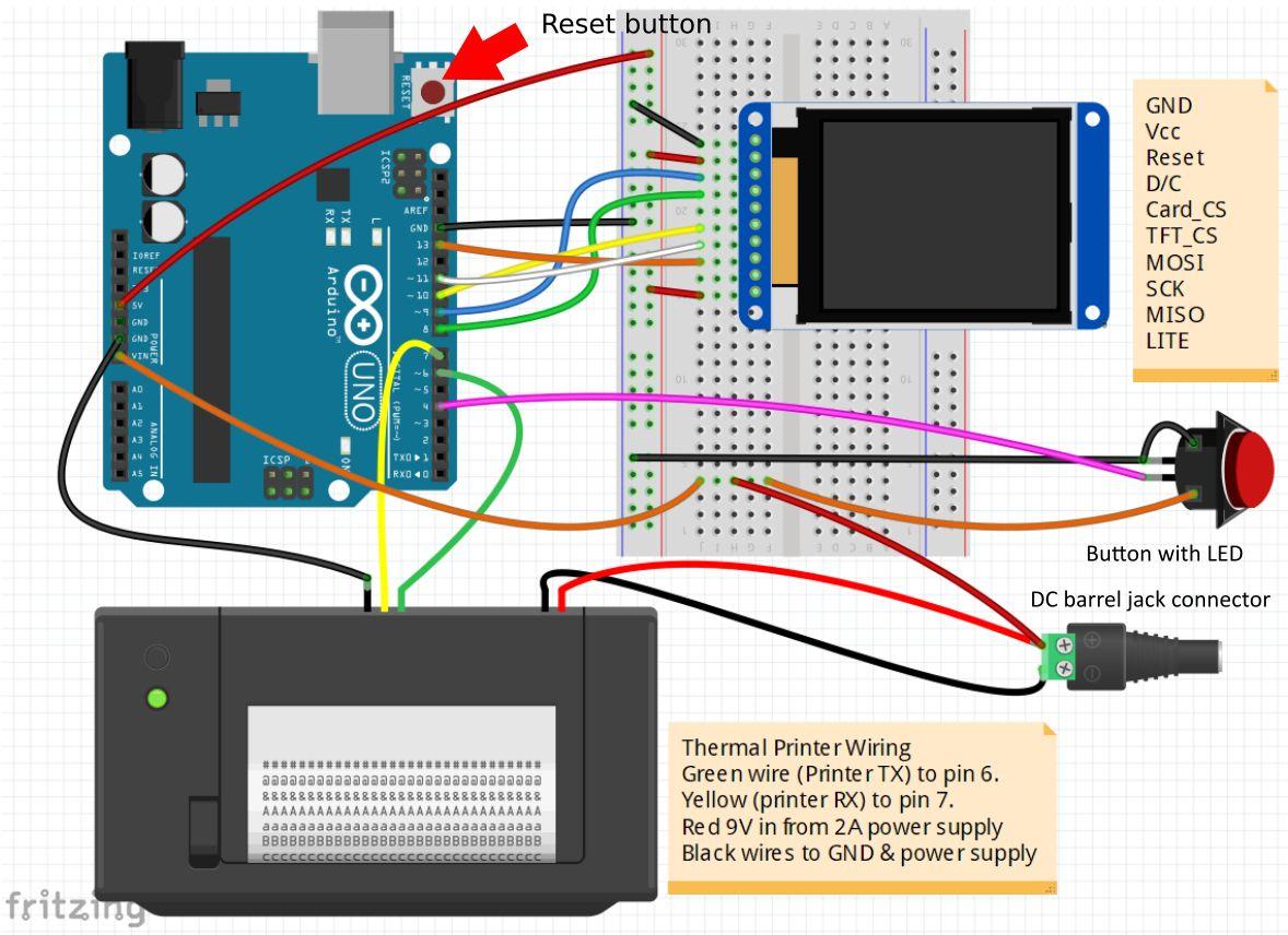
Wire up the printer TTL serial cable with three wires as follows: Black to GND, yellow (printer RX) to pin 7 and green (printer TX) to pin 6 of the Arduino. Now connect the red and black power cables for the printer to the DC barrel jack connector. Red is +9Vdc and black is the GND. Also add an extra red jumper wire to the +9V side of the DC barrel jack connector and connect the other end to Vin on the Arduino–now your machine will run even when the USB cable is not connected.Remember the printer uses quite a bit of power as it prints, so we have to use a 9V power supply that can provide at least 2A. The image below also shows the illuminated push button connected–we will cover that in a bit.
Step 7
Test the thermal printer by keeping its button on the front held down while you power it up with the 9v power supply. It should print out a status page similar to this:
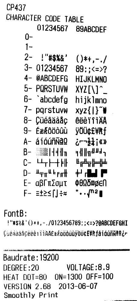
Note the serial baud rate; in this case it is 19200bps, so we use that in our code to communicate with it. You can also see the supply voltage, here it is 8.9v.
Step 8
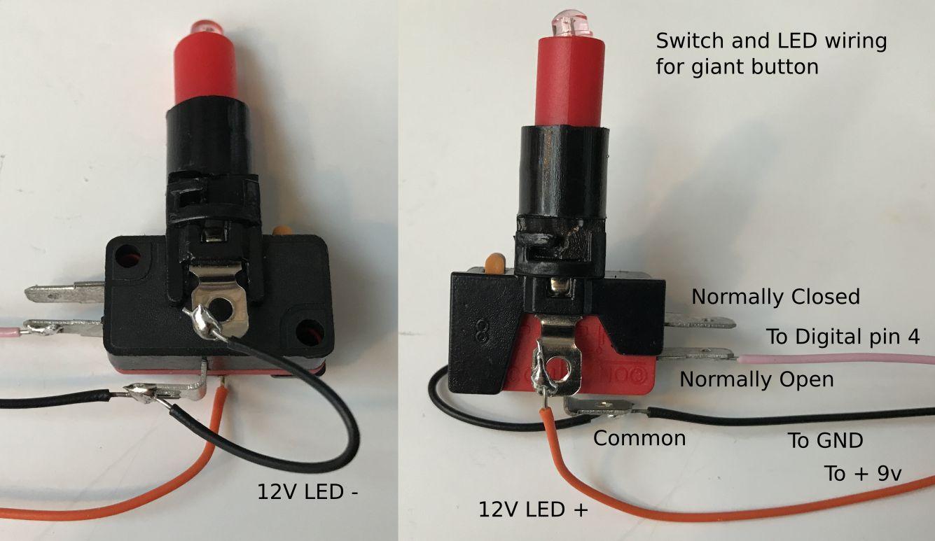
Now the printer is working,we need to wire up the illuminated button. The previous diagrams show the connections–the normally open contact goes to Digital pin 4 on the Arduino, the common goes to GND, the positive (anode) side of the LED and resistor goes to the +9V supply and the negative (cathode)side goes to GND. Note the LED has a resistoral ready soldered onto it so it can safely run it from 5 to 12V. If the button not illuminate, check you have the +9V correctly going to the LED terminal on the red side of switch as show below.
Step 9
Now it is time to upload the main Secret Santa Arduino code. Download it first from the GitHub page for Secret Santa Machine and then open it in the Arduino IDE. At the top of the code is the string people[]. This is the list of the Secret Santa participants. Simply enter each name with inverted commas around it and a comma to separate them.Double check your 9V power supply is plugged in and switched on and then upload the code to your Arduino board and see if it runs, following the prompts on the screen, it should print a ticket for each person. If you get two names where you expect one, you forgot a comma.If you need to run the code again, simple press the reset button.
Step 10
If everything is working, you can mount the machine into a box. To do this you may want to use some of the male to female jumper wires to extend the screen off the breadboard like this:
Step 11
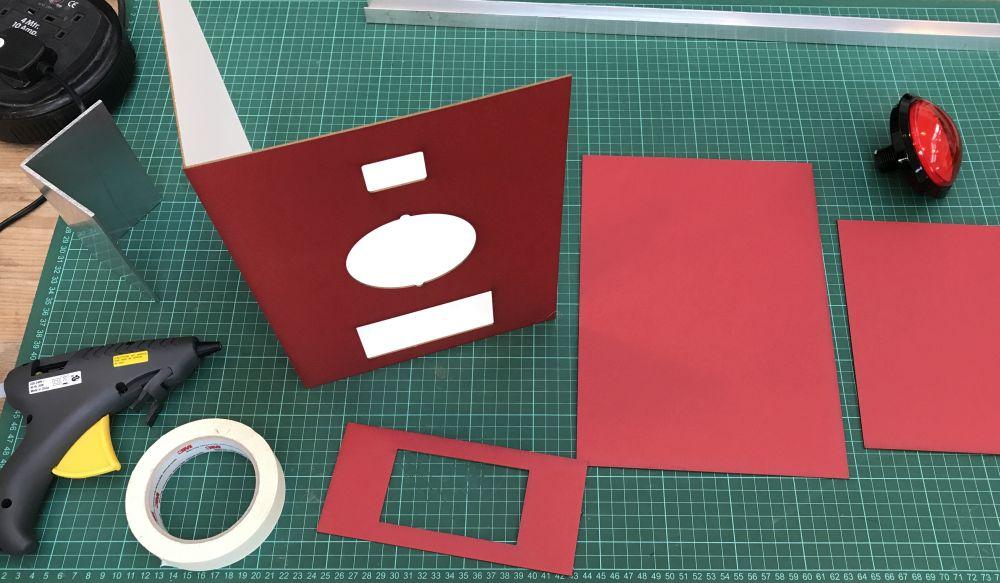
The box can be made out of 1.5mm thick mount board available in almost any colour. There is an EPS file for laser cutting here or in pdf version here or finally just the front panel template you can print out on A4 paper here, just ensure the printer is set to ‘no scaling’rather than the standard ‘fit to size’.
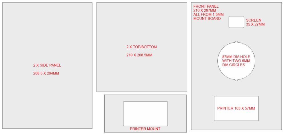
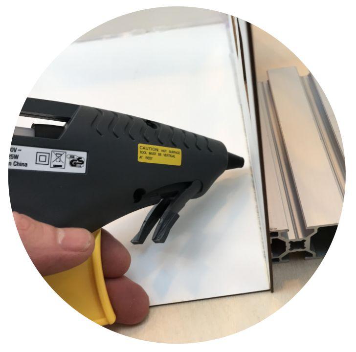
Test the cut outs to check the screen, button and printer fit OK before you fix anything. The mount board can then be carefully joined with a glue gun. It helps to use something to keep the edges square while you glue them. Here there is a piece of aluminium channel, but anything with a flat square edge would help.
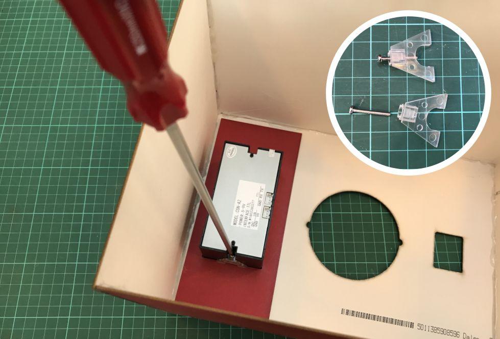
Once the box is assembled, glue the printer mount piece onto the inside of the printer cutout, push the printer in from the front and using the two transparent retaining clips and screws provided with it, clamp it to the box. Your screwdriver doesn’t have to be this long.
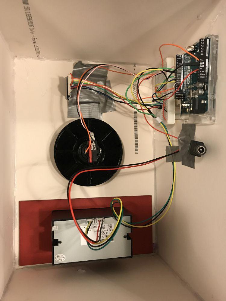
You can now mount the button and start carefully fitting your electronics. Mount the Arduino and breadboard using doubled sized foam tape. Use gaffa tape to strain relief the wires and to mount the screen behind the cut out.
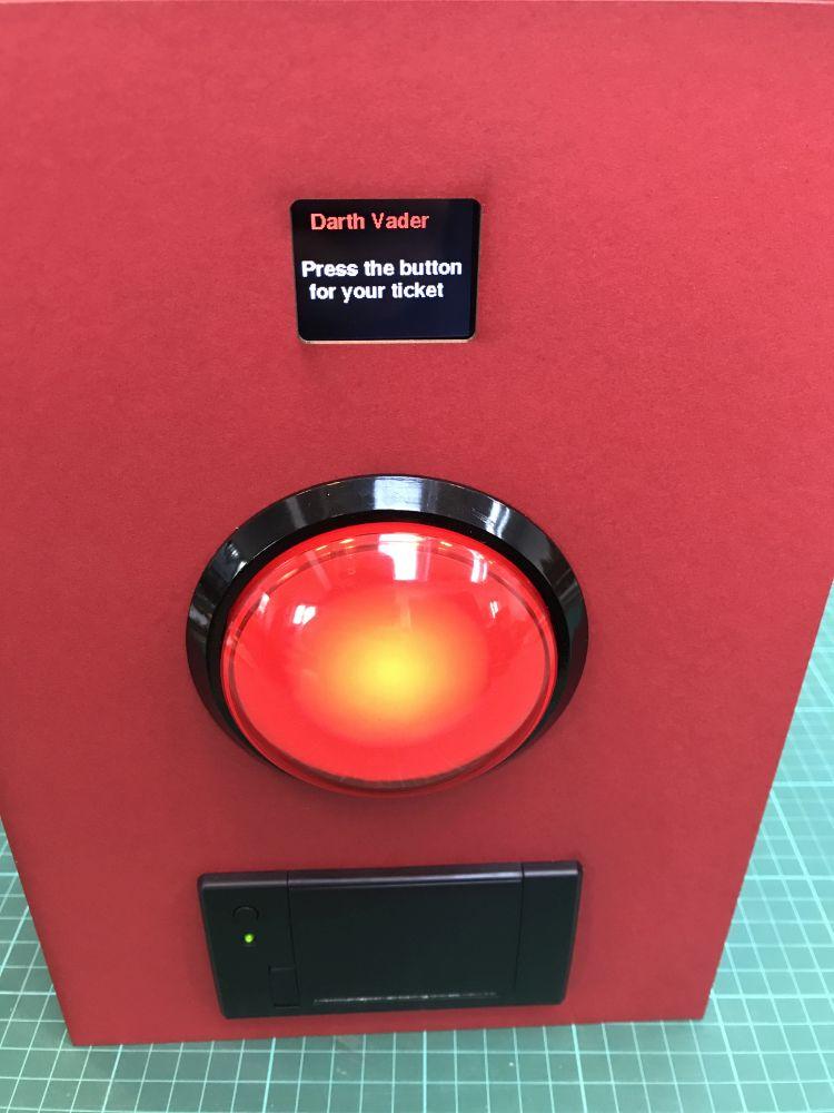
Now it is time to try the machine out.
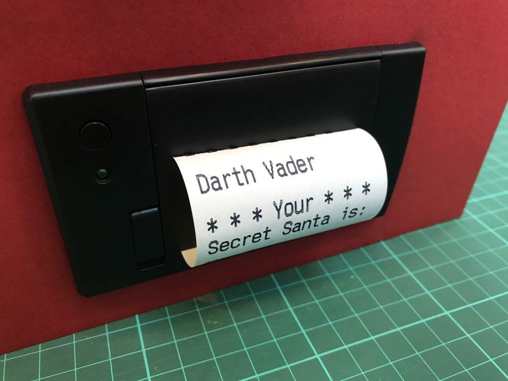
Always carefully tear off the tickets upwards, starting from one edge.
Like what you read? Why not show your appreciation by giving some love.
From a quick tap to smashing that love button and show how much you enjoyed this project.

