Arduino Oplà is a complete IoT product development kit capable of producing slick, professional-looking prototypes for smart applications.
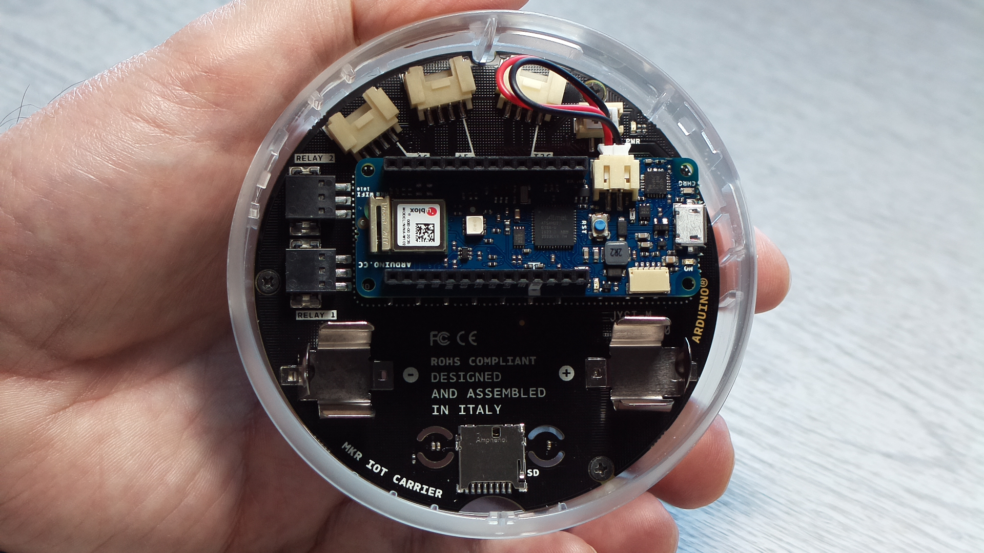
Its small, circular PCB is packed with devices and sensors. There are 5 capacitive touch sensors, a full colour OLED display, 5 RGB LED’s, buzzer, environmental sensors for temperature, humidity and pressure plus light and gesture recognition and an IMU.
The carrier board plays host to the MKR range of Arduino SAMD 21 microcontroller boards and the MKR WiFi 1010 is included in the kit, but it’s possible to swap this for any of the other MKR family to give a flexible range of connectivity options like LoRa, NB-IoT or GSM.
A battery clip for a Li-ion battery (not included) is fitted and there are 2x 24V relays built-in and connectors for 2x Grove analogue and 1x I2C external sensors giving access to over 100 additional add-ons, along with an SD card slot. An external Grove soil moisture sensor and PIR sensor are included and a USB programming cable.
The whole thing is housed in an attractive translucent case with a backing plate that can be surface mounted or free-standing.
In addition, the kit includes 1-years free access to the Arduino Web Editor for programming the device and the Arduino IoT Cloud for building IoT dashboards, plus there are 8 purpose built projects with high quality online documentation and code examples.
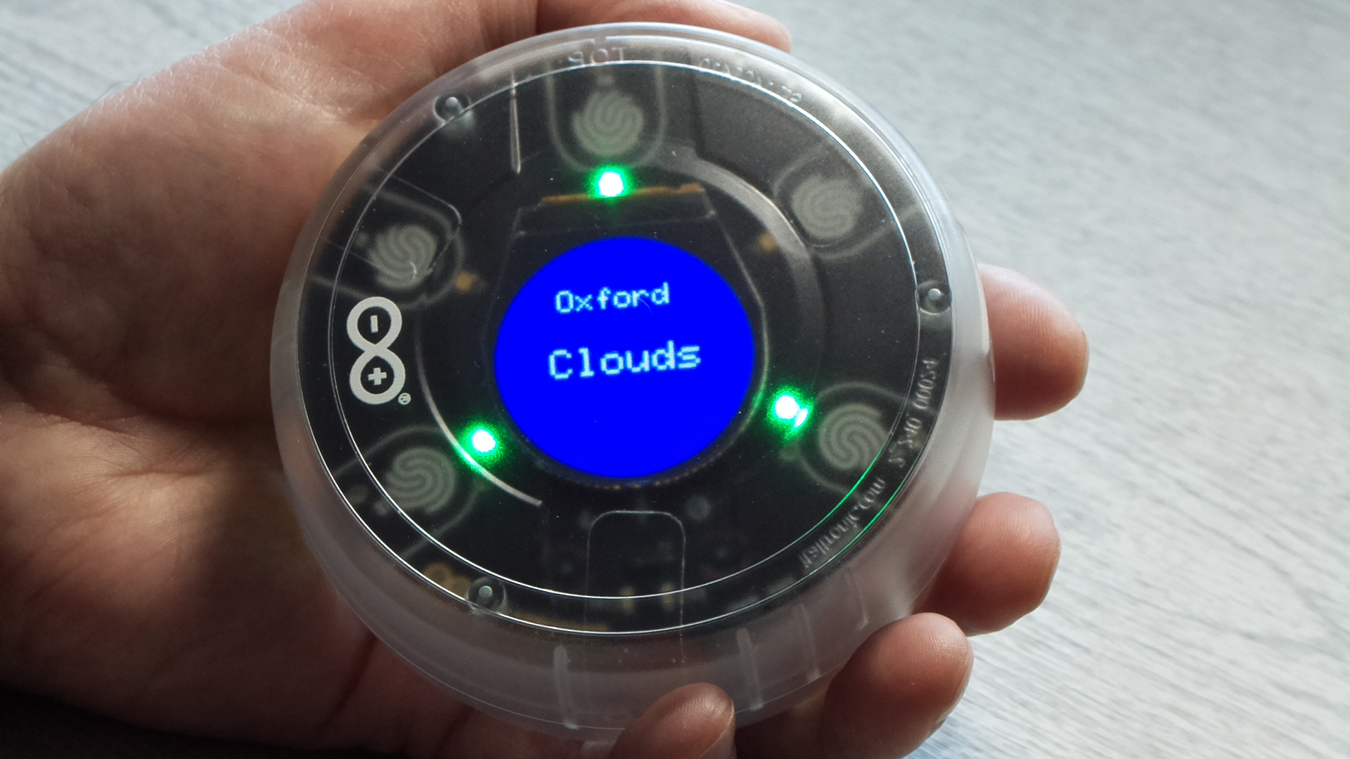
For this project we take you through building a SMART battery powered device which connects via WiFi to the OpenWeather forecast API. It uses the touchpad sensors with pulsing LED indicators and audible touch feedback to display the latest weather forecast for your area along with the indoor temperature from the onboard sensor.
1. Kit Assembly
All the parts required are included in the kit for this project, except a 3.7V Li-ion battery if you want to use the Oplà standalone. Arduino have created very clear instructions for assembling the Oplà kit which you can find here. Below is an overview:
- Attach the MKR Wifi 1010 board to the sockets on the underside of the carrier board. Make sure the pin markings on the MKR 1010 match those on the carrier.
- Connect the short black and red, 2-pin cable to the connectors on the MKR 1010 and carrier.
- Align the carrier slot with the spacer on the case and screw in the 3 cross-head retaining screws.
- Attach the supplied USB cable to the MKR and your PC.
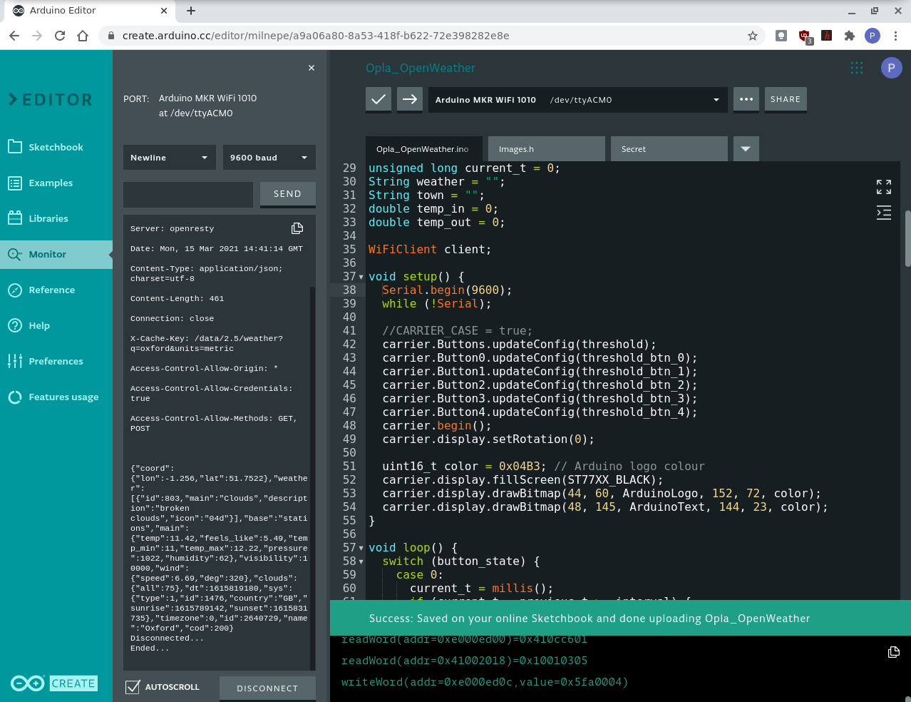
2. Arduino web editor
Included with the Opla Kit is a free 1 Year subscription to the online Arduino development environment. This includes a Web Editor for writing and building your Arduino C/C++ code. It also includes access to the Arduino Cloud for creating Dashboards for your connected devices.
You will need an Arduino account and a plugin agent installing on your PC:
- Visit www.arduino.cc/ and sign in or create an account
- Go to create.arduino.cc/getting-started/plugin/welcome and follow the steps to install the agent for your OS
- Now visit create.arduino.cc/editor/ and login to the editor
The editor also has some nice features like bracket matching and error highlighting and integrated serial monitor. You also have access to hundreds of example projects and libraries.
Now you can access your Arduino projects from anywhere and benefit from having the latest library versions always up to date.
Test that everything is working by uploading the Blink sketch from the Examples menu.
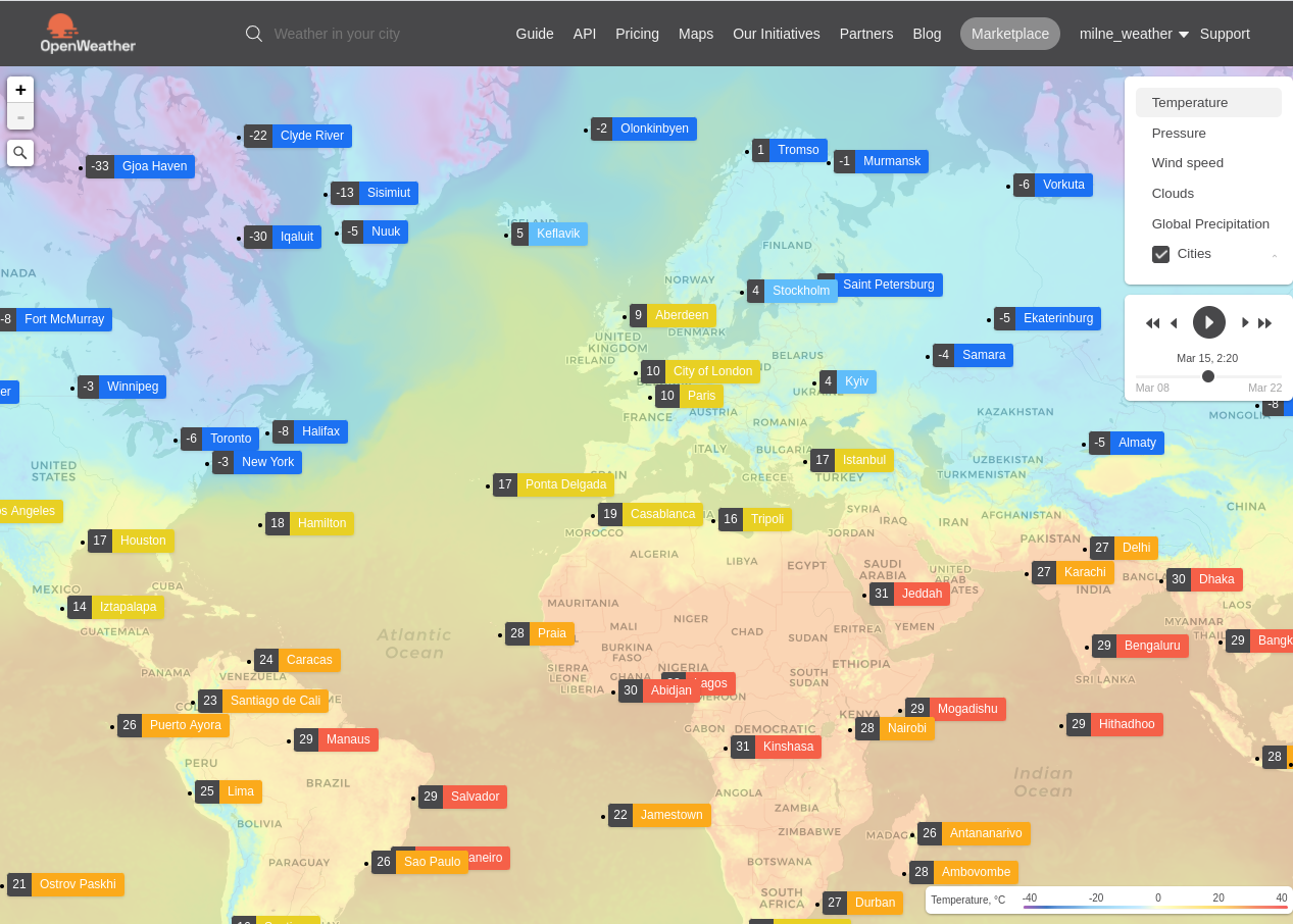
3. OpenWeather Service
OpenWeather provides a weather forecasting service that can be integrated into your IoT project using an easy to use API. The service has a free tier for developers, we used their hourly forecast API:
- Visit openweathermap.org and sign in or create an account.
- Go to your account page and make a copy of the default key. It will be used in your code to authenticate requests to the OpenWeather service.
OpenWeather can provide accurate forecasts in locations around the globe.
4. App design
Once all the components are in place, more detail can be added to the design. We want to create a simple app that can display weather forecasts and outdoor temperature for our location and show the indoor temperature. We also want a clean looking UI that’s intuitive and easy to use.
The Oplà Kit comes with 8 ready to go projects that cover most aspects of the Carrier board features, so you can use these to get a head-start on creating your own apps. Here are the features we used in the project:
Touch sensitive UI with 3 display functions:
- Update latest weather forecast and outdoor temperature from OpenWeather.
- Display outdoor temperature.
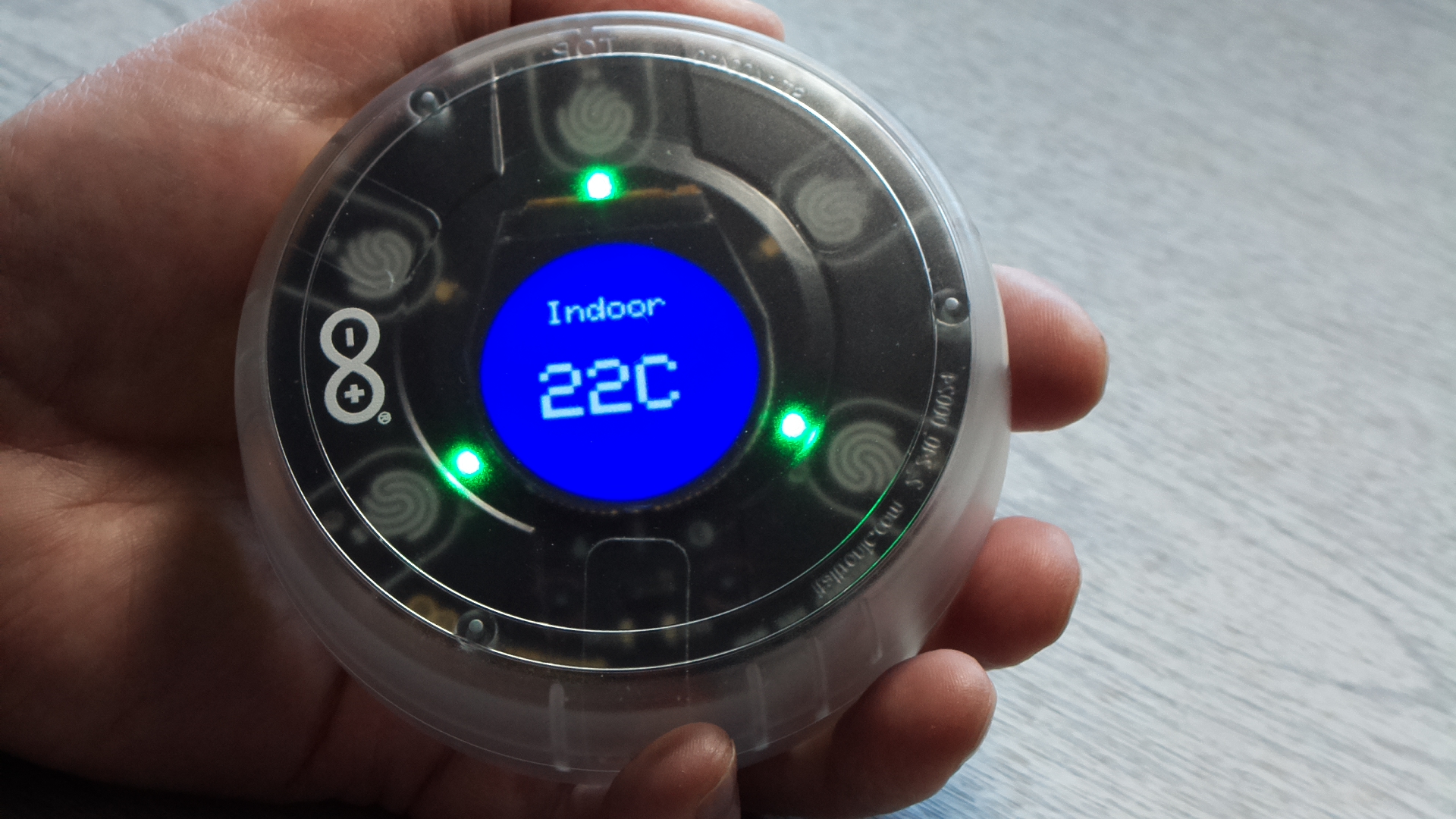
- Display indoor temperature for the on-board sensor.
Battery powered – so conserve energy use
- Connect to WiFi and disconnect after the update.
- Turn the OLED screen backlight off after time-out.
- Indicate active touchpads using LED – pulse to save power.
Boot screen with Arduino logo and custom colours
Audible beep for touch feedback
5. Setup code
The full source code for the project is available on the OKdo GitHub and can be imported directly into the Arduino Web Editor to test it out, or use it as a basis for your own app.
This section highlights some of the setup code which runs just once on startup.
Arduino has created a dedicated library, Arduino_MKRIoTCarrier for the carrier, to make it easier to use the sensors and devices on board. The header for this and the other libraries used are included at the start. An instance of the MKRIoTCarrier class is also created.
#include <Arduino_MKRIoTCarrier.h>
#include <WiFiNINA.h>
#include <Arduino_JSON.h>
#include "Images.h"
MKRIoTCarrier carrier;
...
To use the touchpads with the case on, we found it necessary to override the default settings used in the Carrier library so we could calibrate each touchpad individually. Do this using the updateConfig method for all the buttons then override each button individually. The pads (buttons) must be configured before calling carrier.begin. Setting the pad sensitivity too low results in random touches being triggered and setting it too high makes it unresponsive.
 //CARRIER_CASE = true;
  carrier.Buttons.updateConfig(threshold);
  carrier.Button0.updateConfig(threshold_btn_0);
...
  carrier.begin();
The Web Editor has a special facility if you need to embed private passwords and keys in your code. Declaring a char array as SECRET_XXX causes the editor to create a separate header file to hold the secret values. These are blanked out if you ever export your sketch which is handy. Just put your own wifi credentials, OpenWeather key and location in the Secrets tab.
char ssid[] = SECRET_SSID;
char pass[] = SECRET_PASSWD;
…
When the device starts up we wanted to show the Arduino Logo ( you can also create your own ) so this is included at the end of setup using the drawBitmap method. The actual bitmaps for the logo and logo text are stored in a separate file (Images.h) and loaded into flash memory to save SRAM. It would also be possible to store images on an SD card and load them when required, for example, if you wanted to display an image that represented the current forecast.
carrier.display.drawBitmap(44, 60, ArduinoLogo, 152, 72, color);![]()
6. Main loop
The main loop runs continuously and for the touchpads to be responsive, needs to be non-blocking. We chose to write this as a state machine using a switch/case statement. Most of the time the code is in the initial state which checks the touch sensors. If a touch is detected, the next time through the loop the code changes to the state responsible for executing tasks associated with that touchpad. Once those tasks have finished, it returns to the initial state.
void loop() {
  switch (button_state) {
    case 0:
      ...
      carrier.Buttons.update(); // Check touch pads
      if (carrier.Button0.onTouchDown()) {
        button_state = 3;
      }
      ...
Some states like the WiFi connection, block. They must complete before the touchpads can become active again.
case 1:
      showButtonLed(2);
      showText("Updating");
      connectWiFi();
The changeState function at the end of each case statement transitions back to the initial state. We found a slight delay was necessary before enabling the touchpads again for stability. The function also resets the timer for the backlight so that it will turn off at a set interval after returning.
void changeState(const int state) {
  previous_t = millis();
  button_state = state;
  delay(250); // Delay for stability
}
When the update touchpad is activated, the system connects to Wifi. A GET request to the OpenWeather API is constructed and sent. The location for the weather forecast and the secret key are obtained from the secret array variables.
void requestData() {
  if (client.connect(server, 80)) {
    // Make a HTTP request:
    client.print("GET ");
    client.print("/data/2.5/weather?q=");
    client.print(weather_loc);
...
The response contains the weather forecast and outside temperature as a JSON string. The parseData function parses this and extracts the relevant objects into variables for use in the display.
while (client.connected()) {
    line = client.readStringUntil('n');
    JSONVar myObject = JSON.parse(line);
     weather = JSON.stringify(myObject["weather"][0]["main"]);
...
The weather forecast is displayed before disconnecting the Wifi to save energy and returning to the initial state.
Several functions were written for the Oled display to format the information nicely. They set the background and text colours and position the cursor before updating the display.
void showWeather(String town, String weather) {
  carrier.display.fillScreen(ST77XX_BLUE);
  carrier.display.setCursor(60, 50);
  carrier.display.setTextColor(ST77XX_WHITE);
...
The carrier has several onboard sensors, a temperature and humidity sensor, a light sensor, accelerometer and gyro. It’s also possible to connect various Grove analog and I2C sensors. We included a function to read the temperature sensor before displaying it.
void updateSensors() {
  temp_in = carrier.Env.readTemperature();
}
The final item of note is the pulsing LEDs. The carrier has 5 RGB LEDs positioned next to the touchpads which can be addressed individually or as a set. We used the builtin sin function to vary the brightness of the LEDs so they pulse, indicating which touchpads are active. Each iteration of the main loop increases the LED brightness slightly upto a maximum value before decreasing it again. This makes the code appear to multi-tasking, pulsing the LED’s and detecting touches when in fact the functions are interleaved.
void pulseLoop() {
  static unsigned int i = 0;
  const int max_brightness = 10;
  // Convert mod i degrees to radians
  float b = (i++ % 180) * PI / 180;
  b = sin(b) * max_brightness;
...
7. Battery power
This project was designed to be battery powered so the Oplà can be freestanding.
- Comment out the begin and while loop for the serial monitor and upload.
//Serial.begin(9600);
//while (!Serial);- Remove the USB cable.
- Insert a 3.7V 18650 Li-ion battery into the battery clip making sure the polarity is correct.
- Oplà will show the boot screen and start running.
- Attach the case bottom.
To charge the battery, plug in the USB cable and the CHRG LED on the MKR 1010 will light up. It will go out once charging is completed.
Summary
The Oplà IoT Kit is a great place to start building functional IoT devices that look and feel like real products.
There is so much functionality and flexibility built in to realise any number of possibilities for creating smart devices for which this project is a working example.
Arduino has put a lot of effort into both the product, supporting libraries and online documentation to help beginners and experts alike realise their next IoT smart device.
Like what you read? Why not show your appreciation by giving some love.
From a quick tap to smashing that love button and show how much you enjoyed this project.

