Rotary encoders are extremely useful yet notably hard to implement so that you get stable readings. This project will show you the basics to get a solid input from your rotary encoder.
1. Build the circuit
There are rotary encoders with and without push-button action. For this project, you can use either variant as we’ll only be using the rotary function. As encoders may vary, always check your specific encoder’s documentation but generally they will have 3 contacts for the rotary action and 2 for the push-button which we’ll ignore from now on. Generally, the middle contact will be ground, while the other 2 will correspond to turning left and turning right.
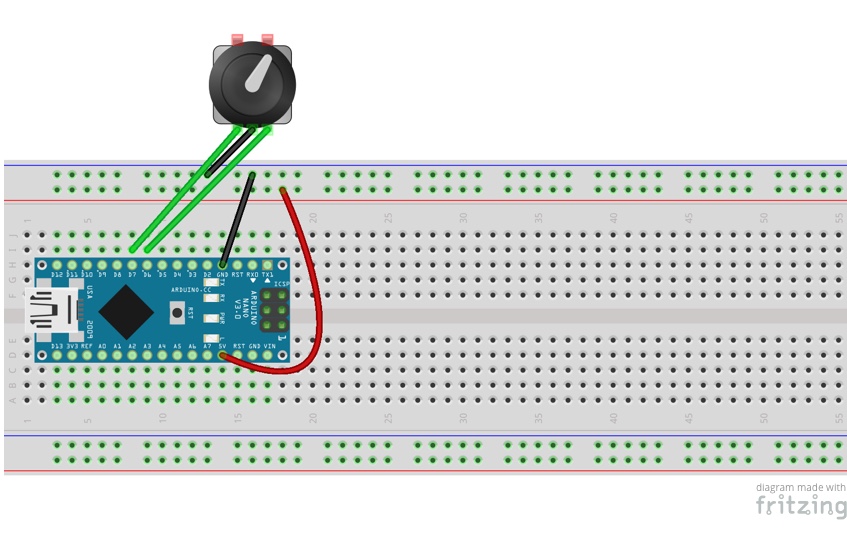
- Connect the Arduino to the breadboard bridging over the central canal.
- Connect the GRN pin of the Arduino to the ground rail on the breadboard.
- Connect the 5V pin of the Arduino to the live rail on the breadboard.
- Connect the ground connector of the encoder to the ground rail of the breadboard.
- Connect the left connector of the encoder to pin D7 on the Arduino.
- Connect the right connector of the encoder to pin D6 on the Arduino
2. Load the code
- Open Arduino IDE on your host computer. You can download it from here.
- Connect the Arduino to your host computer with the mini USB cable.
- In Arduino IDE, go to Tools>Board and select Arduino Nano.
- In Arduino IDE, go to Tools>Processor and select Atmega328P (Old Bootloader).
- In Arduino IDE, go to Tools>Port and select Atmega328P (Old Bootloader).
- Open a new Arduino sketch and paste the following code:
/* Rotary encoder handler for arduino.
 *
 * Copyright 2011 Ben Buxton. Licenced under the GNU GPL Version 3.
 * Contact: bb@cactii.net
 *
 * Quick implementation of rotary encoder routine.
 *
 * More info: http://www.buxtronix.net/2011/10/rotary-encoders-done-properly.html
 *
 */

// Half-step mode?
#define HALF_STEP
// Arduino pins the encoder is attached to. Attach the center to ground.
#define ROTARY_PIN1 7
#define ROTARY_PIN2 6
// define to enable weak pullups.
#define ENABLE_PULLUPS
 int encoderCount;

#ifdef HALF_STEP
// Use the half-step state table (emits a code at 00 and 11)
const char ttable[6][4] = {
  {0x3 , 0x2, 0x1,  0x0}, {0x83, 0x0, 0x1,  0x0},
  {0x43, 0x2, 0x0,  0x0}, {0x3 , 0x5, 0x4,  0x0},
  {0x3 , 0x3, 0x4, 0x40}, {0x3 , 0x5, 0x3, 0x80}
};
#else
// Use the full-step state table (emits a code at 00 only)
const char ttable[7][4] = {
  {0x0, 0x2, 0x4,  0x0}, {0x3, 0x0, 0x1, 0x40},
  {0x3, 0x2, 0x0,  0x0}, {0x3, 0x2, 0x1,  0x0},
  {0x6, 0x0, 0x4,  0x0}, {0x6, 0x5, 0x0, 0x80},
  {0x6, 0x5, 0x4,  0x0},
};
#endif
volatile char state = 0;

/* Call this once in setup(). */
void rotary_init() {
  pinMode(ROTARY_PIN1, INPUT);
  pinMode(ROTARY_PIN2, INPUT);
#ifdef ENABLE_PULLUPS
  digitalWrite(ROTARY_PIN1, HIGH);
  digitalWrite(ROTARY_PIN2, HIGH);
#endif
}

/* Read input pins and process for events. Call this either from a
 * loop or an interrupt (eg pin change or timer).
 *
 * Returns 0 on no event, otherwise 0x80 or 0x40 depending on the direction.
 */
char rotary_process() {
  char pinstate = (digitalRead(ROTARY_PIN2) << 1) | digitalRead(ROTARY_PIN1);
  state = ttable[state & 0xf][pinstate];
  return (state & 0xc0);
}

void setup() {
  Serial.begin(9600);
  rotary_init();
}

void loop() {
  char result = rotary_process();
  if (result)
    Serial.println(result == 0x40 ? "LEFT" : "RIGHT");

    if (result == 0x40){
    encoderCount = -1;
     }else if (result == 0){
    encoderCount = 0;
     }
     else{encoderCount = 1;}


   Serial.println (encoderCount);


}- Load the sketch to your Arduino by pressing on the right-pointing arrow.
- Open Serial Monitor on the Arduino IDE by clicking on the magnifying glass.
- Move the encoder.
You should see Left and Right printed on the output of the Serial Monitor as you move the encoder.
3. Do more
You can go here to find more information about how the code works.
Like what you read? Why not show your appreciation by giving some love.
From a quick tap to smashing that love button and show how much you enjoyed this project.
