Arduino enables you to easily combine a microphone with addressable LED’s to create funky sound-reactive lighting which can be used standalone or as part of a more involved project. This project will introduce you to the FHT library, an awesome resource when you need to analyse incoming audio.
1. Build the circuit
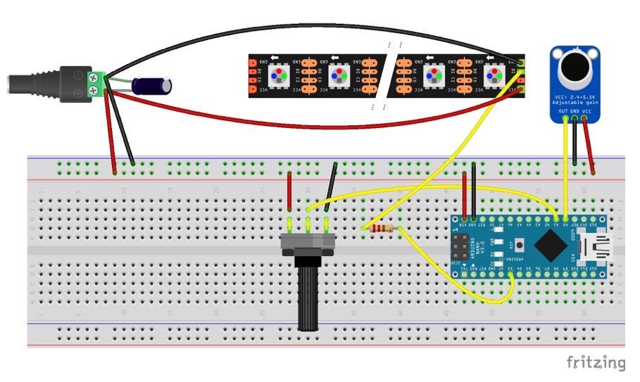
- Connect the Arduino’s GND pin to the ground rail of the breadboard.
- Connect the Arduino’s VIN pin to the live rail of the breadboard.
- Bridge the 1000µF capacitor between the live and ground connectors of the DC connector socket. Ensure that you respect the polarity of the capacitor. The shorter leg marked with an arrow and – should connect to ground.
- Connect the GND connector of the microphone to the ground rail of the breadboard.
- Connect the VCC connector of the microphone to the live rail of the breadboard.
- Connect the OUT connector of the microphone to the A0 pin of the Arduino.
- Connect the GND connector of the LED strip to the ground of the DC connector socket.
- Connect the +5V connector of the LED strip to the live connector of the DC connector socket.
- Connect the BO connector of the LED strip to a pin of the resistor.
- Connect the other pin of the resistor to pin D3 on the Arduino.
- Connect the centre pin of the potentiometer to pin A1 on the Arduino.
- Connect the left pin of the potentiometer to the live rail on the breadboard.
- Connect the right pin of the potentiometer to the ground rail on the breadboard.
- Connect the live cable of the power supply to the live rail of the breadboard.
- Connect the ground cable of the power supply to the ground rail of the breadboard
2. Configure IDE
- On your host computer, go to https://www.arduino.cc/en/main/software and download the correct IDE for your operating system if you don’t already have it.

- Once downloaded, install the package by opening it and following any prompts.
- On the IDE’s menu go to Sketch>Include Library>Manage Libraries.
- In the Library Manager window, type FastLED in the search box.
- When FastLED appears, click on Install.
- Download the ArduinoFHT4 library.
- Once downloaded, open the zip file and place the folder called FHT inside the Arduino’s libraries folder on your host computer.
3. Programme the Arduino
- Connect the Arduino to your host PC with the mini USB cable.
- In Arduino IDE, go to Tools>Board and select Arduino Nano.
- In Arduino IDE, go to Tools>Processor and select Atmega328P (Old Bootloader).
- In Arduino IDE, go to Tools>Port and select Atmega328P (Old Bootloader).
- Open a new Arduino sketch and paste the following code:
#include "FastLED.h"


#define OCTAVE 1 //   // Group buckets into octaves  (use the log output function LOG_OUT 1)
#define OCT_NORM 0 // Don't normalise octave intensities by number of bins
#define FHT_N 256 // set to 256 point fht
#include <FHT.h> // include the library
//int noise[] = {204,188,68,73,150,98,88,68}; // noise level determined by playing pink noise and seeing levels [trial and error]{204,188,68,73,150,98,88,68}


// int noise[] = {204,190,108,85,65,65,55,60}; // noise for mega adk
int noise[] = {204,195,100,90,85,80,75,75}; // noise for NANO
//int noise[] = {204,198,100,85,85,80,80,80};
float noise_fact[] = {15, 7, 1.5, 1, 1.2, 1.4, 1.7,3}; // noise level determined by playing pink noise and seeing levels [trial and error]{204,188,68,73,150,98,88,68}
float noise_fact_adj[] = {15, 7, 1.5, 1, 1.2, 1.4, 1.7,3}; // noise level determined by playing pink noise and seeing levels [trial and error]{204,188,68,73,150,98,88,68}


#define LED_PIN     3
#define LED_TYPE    WS2812
#define COLOR_ORDER GRB


// Params for width and height
const uint8_t kMatrixWidth = 8;
const uint8_t kMatrixHeight = 8;//----------was 27
// #define NUM_LEDS (kMatrixWidth * kMatrixHeight)
#define NUM_LEDS    64

CRGB leds[NUM_LEDS];

int counter2=0;


void setup() {
Serial.begin(9600);
  delay(1000);
  FastLED.addLeds<LED_TYPE, LED_PIN, COLOR_ORDER>(leds, NUM_LEDS).setCorrection( TypicalLEDStrip );

  FastLED.setBrightness (200);
  fill_solid(leds, NUM_LEDS, CRGB::Black);
  FastLED.show();
// TIMSK0 = 0; // turn off timer0 for lower jitter
  ADCSRA = 0xe5; // set the adc to free running mode
  ADMUX = 0x40; // use adc0
  DIDR0 = 0x01; // turn off the digital input for adc0

}


void loop() {
int prev_j[8];
int beat=0;
int prev_oct_j;
int counter=0;
int prev_beat=0;
int led_index=0;
int saturation=0;
int saturation_prev=0;
int brightness=0;
int brightness_prev=0;

 while (1) { // reduces jitter

      cli();  // UDRE interrupt slows this way down on arduino1.0

  for (int i = 0 ; i < FHT_N ; i++) { // save 256 samples
      while (!(ADCSRA & 0x10)); // wait for adc to be ready
      ADCSRA = 0xf5; // restart adc
      byte m = ADCL; // fetch adc data
      byte j = ADCH;
      int k = (j << 8) | m; // form into an int
      k -= 0x0200; // form into a signed int
      k <<= 6; // form into a 16b signed int
      fht_input[i] = k; // put real data into bins
    }
    fht_window(); // window the data for better frequency response
    fht_reorder(); // reorder the data before doing the fht
    fht_run(); // process the data in the fht
    fht_mag_octave(); // take the output of the fht  fht_mag_log()

   // every 50th loop, adjust the volume accourding to the value on A2 (Pot)
    if (counter >= 50) {
      ADMUX = 0x40 | (1 & 0x07); // set admux to look at Analogpin A1 - Master Volume


      while (!(ADCSRA & 0x10)); // wait for adc to be ready
      ADCSRA = 0xf5; // restart adc
  delay(10);
      while (!(ADCSRA & 0x10)); // wait for adc to be ready
      ADCSRA = 0xf5; // restart adc
      byte m = ADCL; // fetch adc data
      byte j = ADCH;
      int k = (j << 8) | m; // form into an int
      float master_volume=(k+0.1)/1000 +.75;  // so the valu will be between ~0.5 and 1.---------------------+.75 was .5
  Serial.println (master_volume);


      for (int i=1; i<8; i++) {
          noise_fact_adj[i]=noise_fact[i]*master_volume;
      }

      ADMUX = 0x40 | (0 & 0x07); // set admux back to look at A0 analog pin (to read the microphone input
      counter = 0;
    }

    sei();
    counter++;


    // End of Fourier Transform code - output is stored in fht_oct_out[i].

    // i=0-7 frequency (octave) bins (don't use 0 or 1), fht_oct_out[1]= amplitude of frequency for bin 1
    // for loop a) removes background noise average and takes absolute value b) low / high pass filter as still very noisy
    // c) maps amplitude of octave to a colour between blue and red d) sets pixel colour to amplitude of each frequency (octave)

    for (int i = 1; i < 8; i++) {  // goes through each octave. skip the first 1, which is not useful

      int j;
      j = (fht_oct_out[i] - noise[i]); // take the pink noise average level out, take the asbolute value to avoid negative numbers
      if (j<10) {j=0;}
      j= j*noise_fact_adj[i];

      if (j<10) {j=0;}
      else {
        j= j*noise_fact_adj[i];
        if (j>180) {
          if (i>=7) {
            beat+=2;
          }
          else {
            beat+=1;
          }
        }
        j=j/30;
        j=j*30; // (force it to more discrete values)
      }

      prev_j[i]=j;

//     Serial.print(j);
//     Serial.print(" ");


// this fills in 11 LED's with interpolated values between each of the 8 OCT values
       if (i>=2) {
        led_index=2*i-3;
        prev_oct_j=(j+prev_j[i-1])/2;

        saturation=constrain(j+50, 0,255);//-----------50 was 30
        saturation_prev=constrain(prev_oct_j+50, 0,255);
        brightness=constrain(j, 0,255);
        brightness_prev=constrain(prev_oct_j, 0,255);
if (brightness==255) {
  saturation=50;
  brightness=200;
}
if (brightness_prev==255) {
  saturation_prev=50;
  brightness_prev=200;
}


        for (uint8_t y=0;y<kMatrixHeight;y++){
          leds[XY(led_index-1,y)] = CHSV(j+y*30,saturation, brightness);
          if (i>2){
            prev_oct_j=(j+prev_j[i-1])/2;
            leds[ XY(led_index-2,y)]=CHSV(prev_oct_j+y*30,saturation_prev, brightness_prev);
          }
        }
       }
    }


      if (beat>=7) {
          fill_solid(leds, NUM_LEDS, CRGB::Gray);
          FastLED.setBrightness(200);


      }
    else {
      if (prev_beat!=beat) {
        FastLED.setBrightness(40+beat*beat*5);
        prev_beat=beat;
      }

    }

    FastLED.show();
    if (beat) {
      counter2+=((beat+4)/2-2);
      if (counter2<0) {counter2=1000;}
      if (beat>3 && beat<7) {
         FastLED.delay (20);
      }
      beat=0;
    }

// Serial.println();
 }
}


// Param for different pixel layouts
const bool    kMatrixSerpentineLayout = false;
// Set 'kMatrixSerpentineLayout' to false if your pixels are
// laid out all running the same way, like this:

// Set 'kMatrixSerpentineLayout' to true if your pixels are
// laid out back-and-forth, like this:

uint16_t XY( uint8_t x, uint8_t y)
{
  uint16_t i;

  if( kMatrixSerpentineLayout == false) {
    i = (y * kMatrixWidth) + x;
  }

  if( kMatrixSerpentineLayout == true) {
    if( y & 0x01) {
      // Odd rows run backwards
      uint8_t reverseX = (kMatrixWidth - 1) - x;
      i = (y * kMatrixWidth) + reverseX;

    } else {
      // Even rows run forwards
      i = (y * kMatrixWidth) + x;

    }
  }

  i=(i+counter2)%NUM_LEDS;
  return i;
}- Load the sketch to your Arduino by pressing on the right-pointing arrow.
- Connect the 5VDC power to your circuit.
- Play some music.
After a few seconds, the LED strip will start reacting to the music. You can adjust the sensitivity using the potentiometer. You can also adjust the sensitivity by turning the small dial on the reverse of the microphone using a small Philips screwdriver.
4. Do more
Once you have it all up and running, you could start tweaking the code, adjusting variables to your liking.
If you intend to use this project ongoingly or you want to fit it to your personal dancefloor, it would be wise to transfer it to stripboard and house it in a little box.
If you want to dig a little deeper, you can refer to the FHT library which is what analyses the incoming audio. You can find more about it here.
Like what you read? Why not show your appreciation by giving some love.
From a quick tap to smashing that love button and show how much you enjoyed this project.

