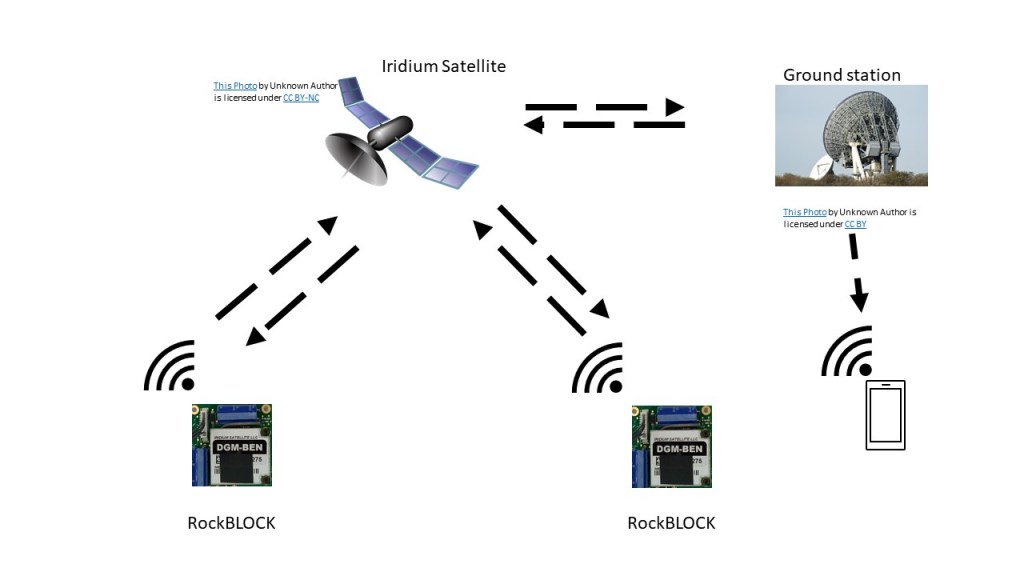
This project shows how to send GPS positioning messages from one RockBLOCK to another via satellite link, allowing 2 devices to connect from anywhere on the planet or in the air.
The project uses a Raspberry Pi Pico as a host controller for the RockBLOCK modem and a Grove GPS module for sending real-time GPS positioning. This information is beamed via the Iridium satellite network in the form of a loopback test to demonstrate how messages can be sent and received between devices or forwarded to web-based and mobile applications.
The firmware running on the Pico was developed on a Raspberry Pi400 host in C/C++ using VSCode, and the full source code is available on the OKdo GitHub.
Step 1: RockBLOCK 9603
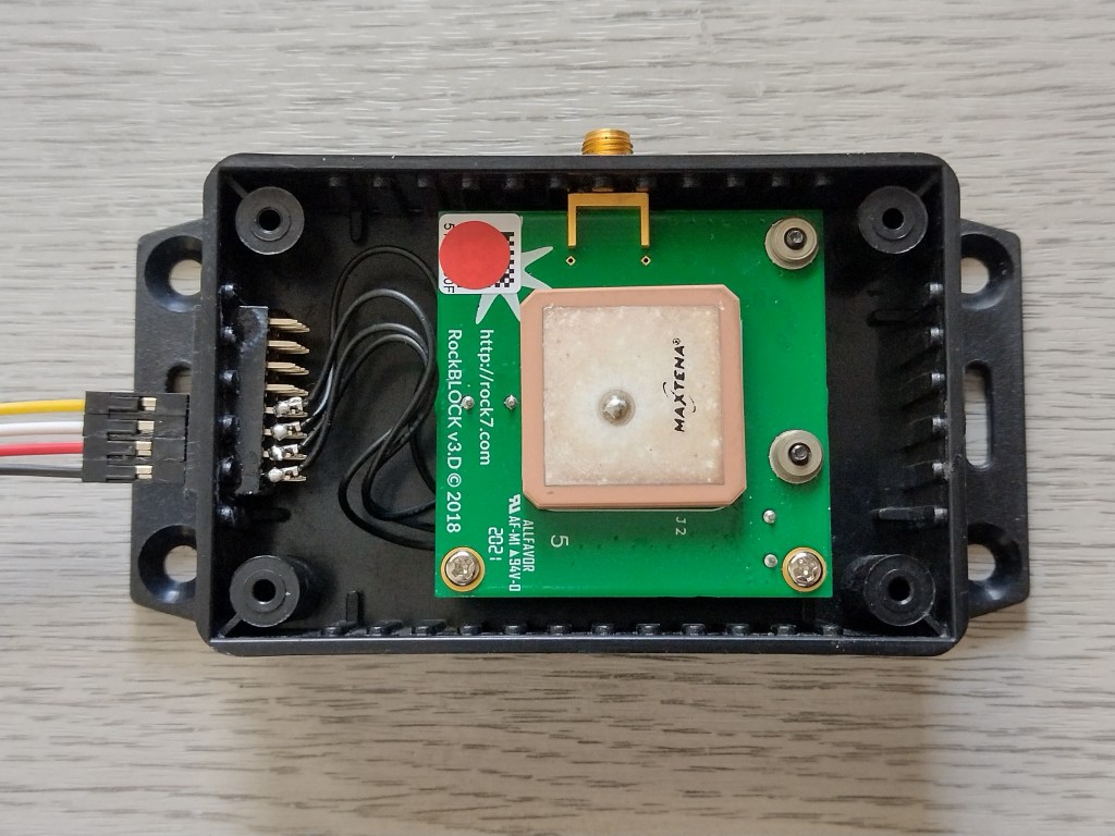
The RockBLOCK 9603 module simplifies the integration of satellite communication into many different applications and products. It provides all the power management components needed for 5V DC or 3.7V Li-ion battery power input and exposes an LVTTL serial interface with an AT command set. The board comes pre-configured with a built-in antenna which we found adequate for testing, and there is also an SMA connector for an external antenna, available separately.
We installed ours in a custom case and soldered the minimal 4 wire TXD, RXD, 5V & GND connections to a female header:
Building a test system for sending messages using the RockBLOCK was covered in a previous project, so in this one, we focus on RockBLOCK to RockBLOCK communication.
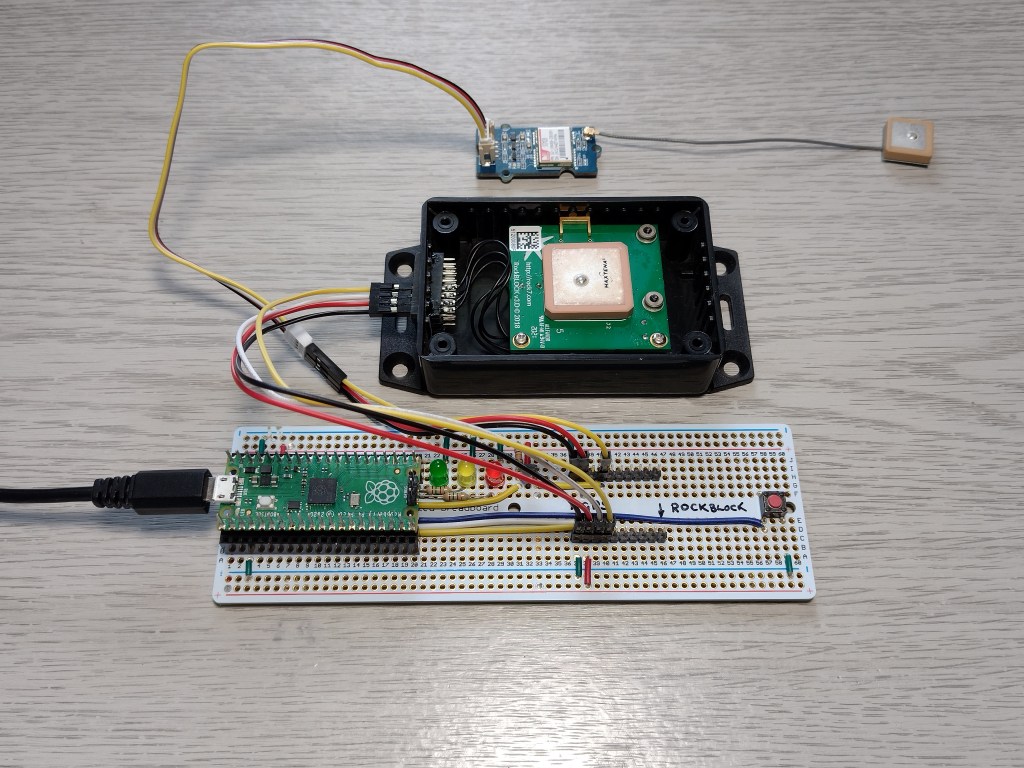
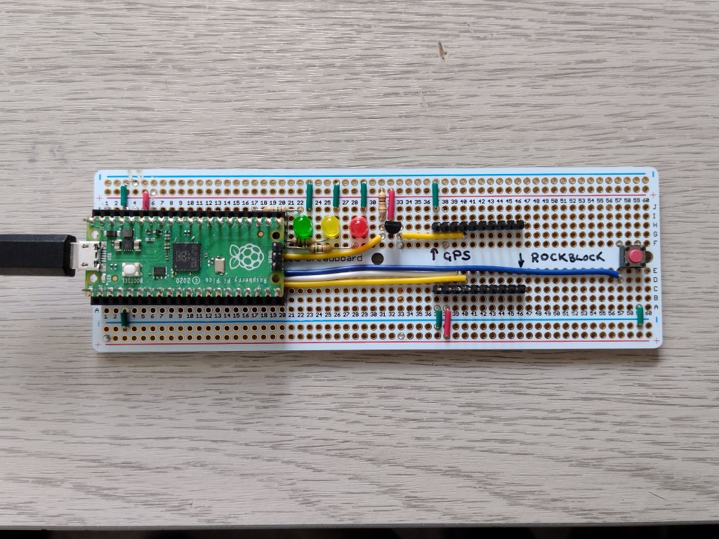
Our test rig consists of a Raspberry Pi Pico microcontroller with UART 1 connected to the RockBLOCK and UART 0 connected to a Grove GPS module.
The RockBLOCK features an LVTTL serial interface operating 3.3V (5V tolerant) with a baud rate of 19200 baud, 8-bits, no parity and 1 stop-bit. The TXD and RXD lines can safely be connected directly to the Pico’s UART pins.
The module has a red power indicator and a solid green LED showing when it’s ready to operate when powered on.
See further details here.
RockBLOCK to Raspberry Pi Pico Connections:
| RockBLOCK Pin | Function | Description | Pico Pin | Function |
| 1 | RXD (3.3V) | Output from RockBLOCK | 7 | UART1 RX (3.3V) |
| 6 | TXD (3.3V) | Input to RockBLOCK | 6 | UART1 TX (3.3V) |
| 8 | 5V | 5V power supply (450mA max) | 40 | VBUS (5V) |
| 10 | GND | Ground | 38 | GND |
Test rig – Pico / RockBLOCK / GPS
Step 2: GPS
Mobile Originating (MO) messages coming from the RockBLOCK have an approximate GPS location attached to them by the receiving satellite. This is used to send ring alerts which can notify the RockBLOCK if there are any Mobile Terminated (MT) messages for the RockBLOCK waiting in the message queue. It is turned off by default, and we did not use the feature, but it is available if required.
If you need accurate GPS positioning, this information must be sent as part of the message payload. We used a Grove GPS module with a serial interface attached to the Pico’s UART 0 and extracted part of the NMEA $GPRMC segment containing the timestamp, latitude and longitude coordinates for our test messages.
Note: The Grove GPS operates at 5V TTL levels, so the TXD output needs level shifting from 5V to 3.3V when connecting to the Pico’s UART. It operates at a 9600 baud.
Warning: Raspberry Pi Pico pins are 3.3V tolerant only. Be careful not to connect any of them to 5V, as this will damage your board.
Grove GPS module to Raspberry Pi Pico serial connections:
| GPS Pin | Function | Description | Pico Pin | Funct |
| TXD | TX (5V) | Output from GPS | 2 | UART0 RX (3.3V) |
| RXD | RX (5V) | Not Connected | ||
| 5V | 5V | Power | 40 | VBUS (5V) |
| GND | GND | Ground | 38 | GND |
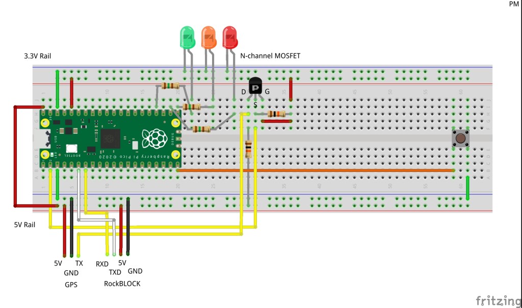
Step 3: Pico Carrier Circuit
We built a carrier board for the Pico using a stripboard for testing. It has 3 LED indicator lights showing message cycle status, a level-shifting N-channel MOSFET for the GPS TXD line and headers to attach the RockBLOCK and GPS cables. A button was used as an input to send a new message.
All the components are powered from the micro USB cable attached to the Pico. The RockBLOCK and GPS modules are powered from the 5V rail on the board connected to the Pico’s VBUS (Pin 40).
Tip: Check the connections carefully before applying power to avoid damage to the Raspberry Pi Pico
Raspberry Pi Pico GPIO connections:
Pico carrier board
Step 4: Message cycle
RockBLOCK uses a modem to send bytes of data over the satellite link, called Iridium Short Burst Data (SBD). The modem has an AT command set that can be used to send either ASCII text or binary data. The overall cycle is the same in both cases, but we will focus on sending text messages.
Outgoing messages from the RockBLOCK to the satellite are called Mobile Oriented (MO) messages, and inbound messages from the satellite are termed Mobile Terminated (MT) messages.
ASCII or Binary MO messages can be up to 340 bytes, and MT messages can be up to 270 bytes.
The modem must receive a predefined sequence of AT commands and have each one acknowledged in order to send and receive messages. Each command must be terminated by the carriage return character (r). The modem would echo back the command and then respond with the characters OK if the command was successful.
Here are the logic and AT commands for a send and receive cycle:
- ATr – check if the modem is ready
- AT&K0r – turn off hardware flow control
- AT+SBDWT=191243.000,A,5147.6348,N,00127.6516,Wr – load message buffer with GPS message
- AT+SBDIXr – start an Extended SBD session to send and receive messages
- Check the response to see if an MT message has been received
- AT+SBDRT – transfer MT message from RockBLOCK message buffer to Pico controller
- Return to idle state
We configured our Pico to display the serial output over the USB connection using minicom:
minicom -b 115200 -o -D /dev/ttyACM0Here is a slightly modified output from a successful send and receive session – the text in italics comes from the program code, and the bold text comes from the RockBLOCK:
READYTOSEND
Message:
182136.000,A,5147.6323,N,00127.6505,W
AT
OK
FLOWCTRL
AT&K0
OK
MOBUFFER
AT+SBDWT=182136.000,A,5147.6323,N,00127.6505,W
OK
SEND
AT+SBDIX
+SBDIX: 0, 30, 1, 5, 10, 0
Message sent
GETMAIL
OK
SENDGOODWAIT
AT+SBDRT
+SBDRT:
Hello BEN!
OK
IDLE
Tip: If you connect the RockBLOCK to a serial to USB cable, you can issue this command sequence in a serial terminal program like minicom as a test. The cable comes with the RockBlock 9603 bundle with FTDI cable.
Although it is simple to send a message manually, the Pico control program must handle many things if it is to succeed. We wrote ours in C++ using Visual Studio Code in a similar way to this getting started guide.
The SWD debugger was very handy for inspecting the message buffer to check for correct line endings.
The rockblock_gps client configures everything, sets up the UARTs and runs main(). The rockblock library code uses the state pattern to send the AT commands and handle the states actions. All the code is Open Source and available on the OKdo GitHub.
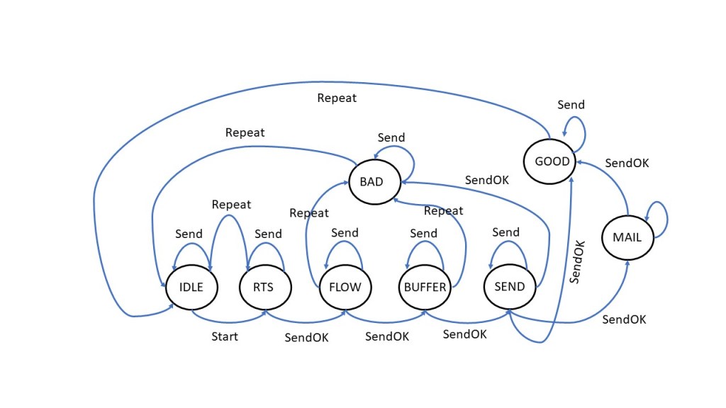
The diagram below shows the different state transitions that occur when sending and receiving messages. Each state is a class and has a set of virtual methods corresponding to actions that either hold the system in its existing state or transition it to the next one.
The Send action issues the AT command for that state and sets a timeout, then waits for the OK response. If the OK arrives, the state is changed; otherwise, it transitions through an error state before returning to IDLE.
When an interrupt fires on the Pico’s RX line, a SendOK action is triggered – the response is analysed, and the next state transition is set accordingly.
The most complicated state is the SEND state. This has to handle multiple responses from the modem according to the success or failure of the transmission and also whether there is an MT message to be received.
During the Extended SBD Session, the modem responds with a coded string containing information about the state of both MO and MT messages.
Here’s what a successful response looks like from a loopback test:
+SBDIX: 0, 21, 1, 2, 46, 0Field 1: MO status – 0 or 1 means success
Field 2: MO message number
Field 3: MT message status – 1 means a new message received
Field 4: MT message number
Field 5: MT message length in bytes
Field 6: Number of messages remaining in the message queue
Full details of how to decode this is in the documentation.
Pico code state transition diagram
Step 5: Sending MT messages
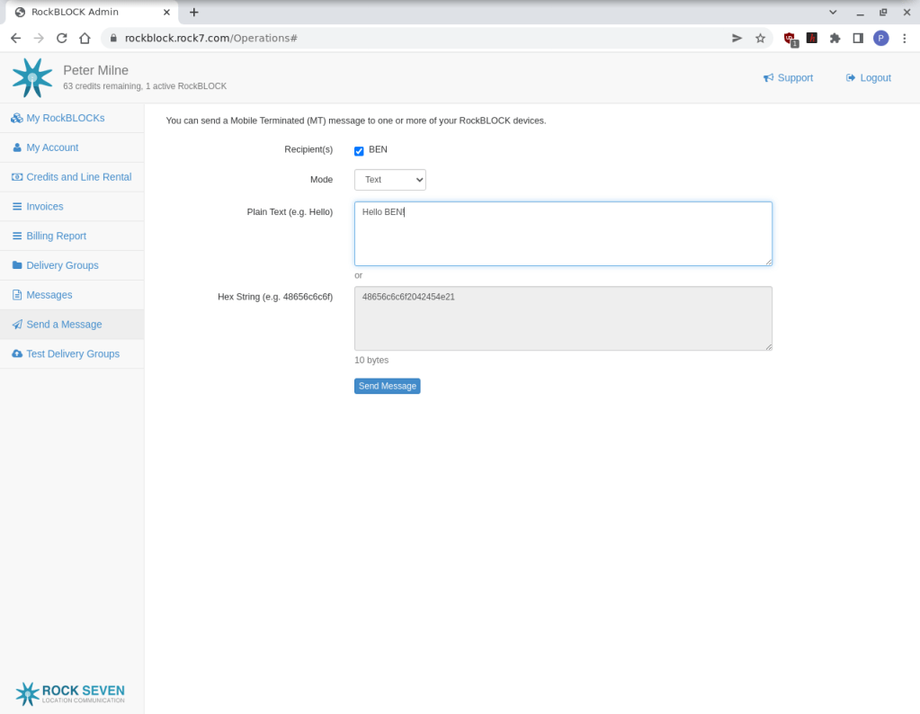
When your RockBLOCK is registered, you get access to a web-based Management Interface. Apart from setting up your device, it has access to billing information, message history and a tool for sending MT data to a device, which is useful for testing purposes.
Here we see a test message being sent to our RockBLOCK. The message is sent directly to the satellite network and is held in the message queue until it is picked up in the next send and receive cycle.
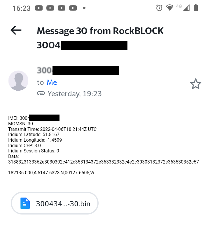
Step 6: RockBLOCK to RockBLOCK messaging
SBD is flexible enough to send messages via the satellite link from one RockBLOCK to another. This means it is possible to send short messages between devices from any 2 points on Earth or in the air!
Firstly both RockBLOCKs need to belong to the same Deliver Group – this is configured in the Management Interface. All that is required is to prefix an MO message with the receiving RockBLOCK’s serial number, and the other device will receive it.
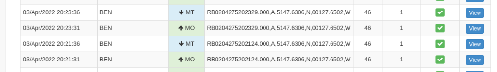
We tested the process by doing a loopback where the MO message was sent from our RockBLOCK in the first Extended SBD session and received back again as an MT message in the next one.
Here you can see the messages going back and forth in our message history:
Step 7: Application integration
The Management interface also allows setting up an email address where any MO messages sent will be forwarded as standard. The response time is generally only a few seconds after the MO message has been sent.
The email alert contains a copy of the message and an attachment in binary format.
There is also an HTTPS API for sending and receiving messages from any third party application using webhooks.
There is an automatic integration with ThingsSpeak if the MO message is formatted correctly and the keys are set up in the Management Interface.
Step 8: Retrying
Since satellite communications rely on line of sight, they are affected by atmospheric conditions like heavy cloud cover, satellite positioning and also contention for resources. Any of these can impact the time it takes to make a connection and complete a message exchange. In some cases, this can take several seconds, and MO messages can often fail to send the first time.
Here’s an example of a message failure response with error code 32, 26 MO messages sent and an MT mailbox error 2:
+SBDIX: 32, 26, 2, 0, 0, 0
message not sent
SENDBADWAIT
If this happens, the message can be retried again immediately, but after 2 attempts, it is advisable to back off incrementally before resending in the following pattern:
After 2 failures, retry after random 0 – 5 seconds, twice
Retry again after random 0 – 30 seconds, twice
Retry again after 5 mins, then repeat
The Pico controller must be able to handle extended response times without blocking execution and handle failure at any point in the data delivery cycle. We demonstrate this by flashing a heartbeat on the Pico’s onboard LED using a timed callback and returning to the idle state on error or message delivery failure.
Summary
The RockBLOCK 9603 module is a very compact solution for communicating via the Iridium satellite network, allowing bi-directional communication for your project from anywhere on Earth or in the air.
Due to its serial interface and simple AT command set, the RockBLOCK can be controlled by many different MCUs and SBCs. It doesn’t come with any library code, so you have to write your own controller application, which we do in this C++ example with the Raspberry Pi Pico.
We show how to choreograph a simple send and receive text message sequence and also perform a loopback test to simulate communication from RockBLOCK to RockBLOCK by exchanging GPS coordinates. The full source code is available on the OKdo GitHub.
RockBLOCK is extremely well documented, easing integration with your hardware and firmware.
Further information is available here.
Like what you read? Why not show your appreciation by giving some love.
From a quick tap to smashing that love button and show how much you enjoyed this project.

