This project will show you how to integrate a Raspberry Pi Pico and RockBLOCK.
When you’re in the middle of nowhere, halfway up Everest or ploughing a field and you need to communicate, then satellite is probably the only viable option. The RockBLOCK 9603 from Rock 7 allows any device with a serial interface to send and receive messages using an Iridium SBD (Short Burst Date) satellite link.
Learn how to connect the RockBLOCK module to the Raspberry Pi Pico microcontroller using its serial uart along with a Grove GPS module which obtains accurate global positioning coordinates, which are sent over the satellite link.
The software that runs on the Pico was developed on a Raspberry Pi400 host in C/C++ using VSCode and the source is open and available on the OKdo github.
1. RockBLOCK Module
The RockBLOCK 9603 PCB assembly hosts an Iridium SBD transceiver, simplifying power requirements, and providing a standard LVTTL serial interface suitable for the Raspberry Pi Pico UART. There’s a built-in antenna on the opposite side of the board, which we used, along with an SMA connector for an external antenna if required.
Using the SMA connector involves carefully removing the Iridium modem temporarily to access the antenna connector. A specialist tuned antenna is required, available separately.
Electrical connection is via a tiny 10-way, Molex PicoBlade 1.25mm pitch connector with mating Molex P/N 51021-1000. We made a cable using pre-crimped 26AWG wire leads (RS P/N 201-9814) and connector (RS P/N 279-9207) soldered to a Grove 4-wire JST lead. This made it easy to attach to either a USB / TTL adapter for testing or to our breadboard circuit.
We used the minimum 4-wire RXD / TXD plus 5V power and GND connections in the project, but there are pins for low power control, network availability, ring alerts (notification of inbound MT messages), hardware flow control and 3.7V Li-Ion battery power.
The serial interface operates at 19200 baud, 8-bits, no parity and 1 stop-bit.
Power requirements are 5.4V(max) at 470mA (max) on the 5V power pin, or 3.7V (5.5V max) at 470mA (max) on the Li-Ion pin.
We powered the RockBLOCK at 5V using the Raspberry Pi Pico VBUS. The Pico was connected via USB cable to a USB 3.0 port on a Raspberry Pi400 host, for programming and testing.
The serial interface operates at 3.3V digital signal levels (LVTTL), which are 5V tolerant so TX and RX can be safely connected directly to the Pico.
When powered on, the module has a red power indicator and a solid green LED showing when it’s ready to operate.
Further details https://docs.rockblock.rock7.com/docs/connectors
RockBLOCK to Raspberry Pi Pico Connections:
| RockBLOCK Pin | Function | Description | Pico Pin | Function |
| 1 | RXD | Iridium 9603N RX (output from RockBLOCK) |
7 | UART1 RX |
| 2 | CTS | Iridium 9603N CTS (output from RockBLOCK) |
||
| 3 | RTS | Iridium 9603N RTS (input to RockBLOCK) |
||
| 4 | NetAv | Network Available signal | ||
| 5 | RI | Ring Indicator signal (active low) | ||
| 6 | TXD | Iridium 9603N TX input to RockBLOCK) |
6 | UART1 TX |
| 7 | OnOff | Sleep control (pull to ground to switch off) |
||
| 8 | 5V in | 5V power supply (450mA limit) | 40 | VBUS |
| 9 | Li-ion | 3.7V power supply (450mA limit) | ||
| 10 | GND | Ground | 38 | GND |
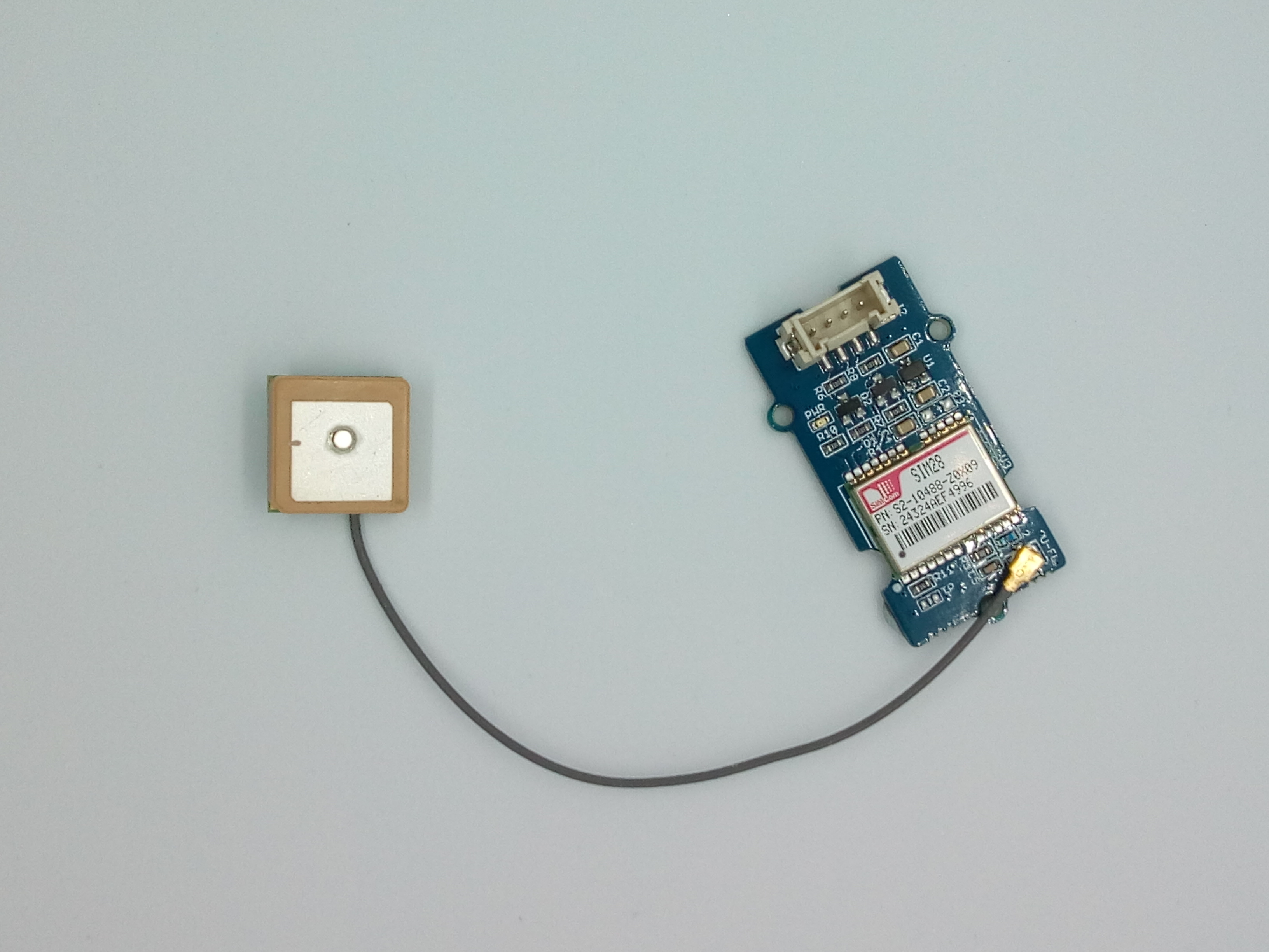
2. GPS
The Grove GPS module outputs a continuous character stream of NMEA (National Marine Electronics Association) compliant GPS sentences over serial at 9600 baud rate. The Raspberry Pi Pico can be programmed to receive, filter and interpret these to obtain an accurate global position.
All Mobile Originating (MO) messages sent from the RockBLOCK have an approximate coordinate location added by the receiving satellite, but for true GPS location this information must be sent as part of the message payload. One of the NMEA sentences output by the Grove GPS is the $GPRMC type. This contains a timestamp, latitude and longitude coordinates, ideal for this purpose.
Further information: https://www.nmea.org/content/STANDARDS/NMEA_0183_Standard
The Grove GPS module operates at 5V, so its TX line needs level-shifting to 3.3V when connecting to the Raspberry Pi Pico GPIO pins.
Raspberry Pi Pico pins are 3.3V tolerant only. Be careful not to connect any of them to 5V as this will damage your board
Grove GPS module to Raspberry Pi Pico serial connections:
| GPS Pin | Function | Description | Pico Pin | Function |
| TX | TX | Output from GPS | 2 | UART1 RX |
| RX | RX | Not Connected | ||
| 5V | 5V in | Power input | 40 | VBUS (5V) |
| GND | GND | Ground | 38 | GND |
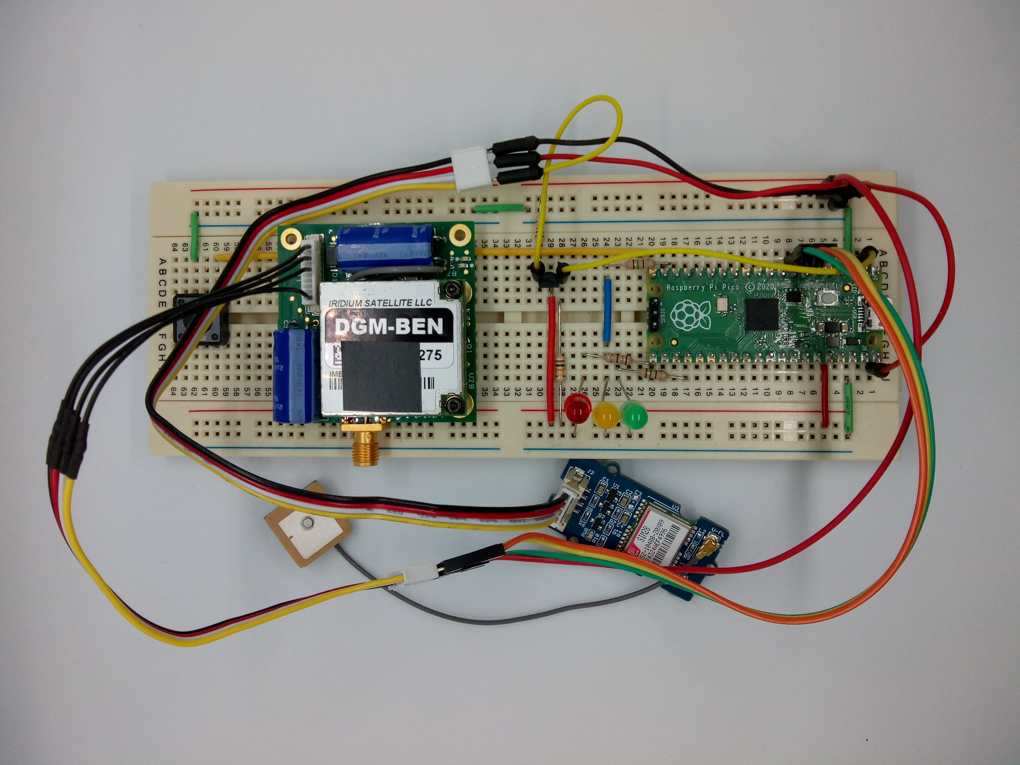
3. Circuit build
Connecting all the components together using a breadboard is straightforward for testing purposes before making a permanent circuit.
We connected the Grove GPS to UART0 and the RockBLOCK to UART1 on the Raspberry Pi Pico. Power and debug output was provided using the Pico’s USB connector.
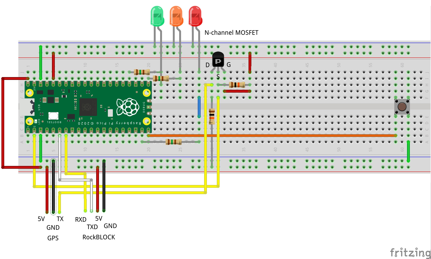
In the diagram below, the top power rail was connected to the Raspberry Pi Pico 3.3V output (Pin 36) for the 3.3V components. The bottom rail is at 5V powering the RockBLOCK and Grove GPS from the Pico VBUS (Pin 40).
An N-channel MOSFET (BS270) level-shifts the GPS TX line down from 5V to 3.3V suitable for the Pico RX connection. Pay attention to the pin-outs on your MOSFET as they are not standardised and may be different to our diagram.
Three LEDs were connected to GPIO outputs giving status information as feedback, and a push-button attached to a GPIO input triggers the message to be sent.
Check the connections carefully before applying power to avoid damage to the Raspberry Pi Pico
Raspberry Pi Pico GPIO connections:
| Pico Pin | Function | Description |
| 19 | GP14 | Red LED (Message failure) |
| 20 | GP15 | Button (input) |
| 21 | GP16 | Amber LED (Waiting for response) |
| 24 | GP18 | Green LED (Ready to send) |
4. RockBLOCK registration
You can power up your RockBLOCK and connect to it, but before you can start transmitting or receiving messages, you will need to register the device with Rock7:
Each device has a unique serial number as an identifier printed on it, which you enter into the registration form after setting up an account.
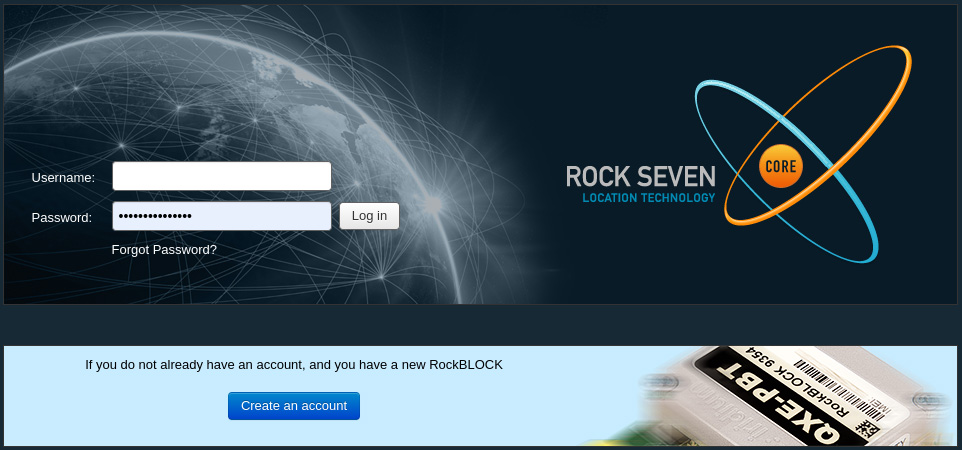
The registration process is very slick and only takes a few minutes before receiving an activation email for your device so you can start using it.
Line rental is paid for in blocks of 1 month, and allows the RockBLOCK to exchange information with the Iridium satellite network. You only pay for months in which you wish to use the RockBLOCK. No annual contract is required. Line rental costs £12.00 per month and includes access to the RockBLOCK Management System for managing your devices.
Credits are used each time you transmit. 1 credit is used per 50 bytes (or part thereof) of message sent or received. We limited our message size to 50 bytes maximum but you can transmit up to 340 bytes and receive a maximum of 270 bytes in each communication.
5. RockBLOCK management
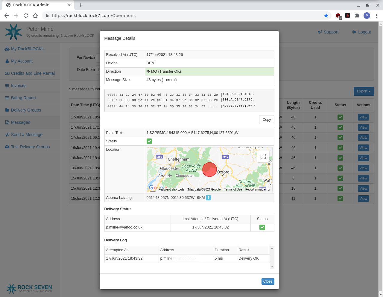
Management of your RockBLOCK devices can be accessed through a web-based management system. This includes registering devices, credits and line rental payments and status, billing and invoicing and message logging.
By selecting a message in the messages view, you can see very detailed information about each message, from payload information to the approximate location where the message was transmitted, displayed on Google Maps.
As part of the service, you automatically receive a copy of the message as an email attachment by default. It’s also possible to route data to and from your RockBLOCK via a well documented HTTP Webhook API. https://docs.rockblock.rock7.com/docs/rockblock-management-system
7. Software
The software running on the Raspberry Pi Pico was developed in C/C++ using the pico-SDK in Visual Studio Code, hosted on a Raspberry Pi400. Detailed instructions on how to do this are in our Getting Started with Raspberry Pi Pico guide.
Download or clone the repo from https://github.com/LetsOKdo/rockblock_gps
- Open the rockblock_gps dir in VSCode
- Configure the project
- Make using debugger
- Open minicom at 115200 baud for the Pico (ttyACMO) in the terminal window:
minicom -b 115200 -o -D /dev/ttyACM0After a few seconds, the green LED should be on, showing that the system is ready. Press the button to initiate a message, the amber LED will turn on indicating that message transmission is in progress. After 20 – 30 seconds either the red LED will turn on, indicating failure or the green LED will come back on indicating success. Each step in the process is shown in the USB output, including the responses from the RockBLOCK.
When the transmission completes, you will receive an email with the message as an attachment (this can take a few minutes) or you can view the details in the online Management system.
The software application is broken down into 3 modules:
- GPS – reads NMEA sentences and filters out the $GPRMC message containing the location coordinates and stores this in a buffer.
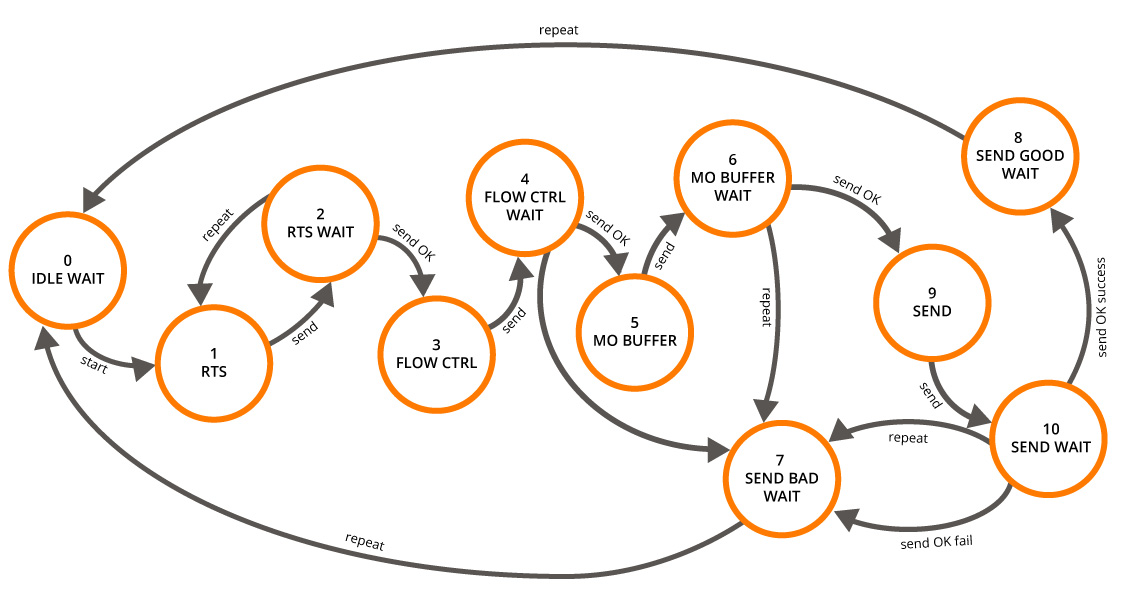
- RockBLOCK – is a state machine managing the AT command sequence detailed in Step 6 above. The process is triggered when the button is pressed and ends in either success or failure before returning back to an idle state.
- Client – manages the setup of UART 0 (GPS) and UART 1 (RockBLOCK), the RX and button interrupts and controls the LEDs. It constructs the message to be sent and continuously cycles the state machine. Further functionality can be added into the main function, providing it is non-blocking.
The state machine sequence is described to the State Transition diagram below:
Summary
The RockBLOCK 9603 module is one of the best products that we have used recently as it worked straight out of the box with no issues and has a really slick web-based management system.
The most difficult part of the project was writing the serial driver software for the Raspberry Pi Pico as there are no libraries that we know of to simplify this yet, although there is a library written for Arduino devices to act as a reference.
In this project, we demonstrated how to build a GPS position tracking device that transmits via satellite link. This system can work anywhere on the planet with a clear view of the sky. So even in very remote locations, you would be able to send your position and a message or any other sensor data via the link.
We used the standard message delivery by email, but Rock 7 has a web service API allowing message forwarding to any web application, making this an extremely flexible solution.
Rock 7 has provided excellent online documentation of every aspect of the RockBLOCK to make it as easy as possible to integrate the module into your project:
Like what you read? Why not show your appreciation by giving some love.
From a quick tap to smashing that love button and show how much you enjoyed this project.

