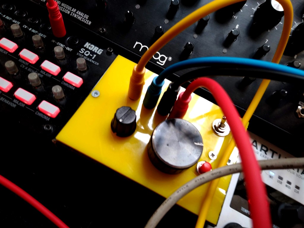
A CV clock with multiple divisions is a great tool to use with your analogue synths and drum machines, whether Eurorack, Volcas, Moog…
In this project, you’ll learn how to make a clock which outputs your BPM together with /2, /4 and /8. The BPM is set via tapping or through an encoder and it has variable pulse length, making it an extremely versatile device which is way cheaper than getting a ready-made one plus you can adapt the code to your needs any time!
1. Build the circuit
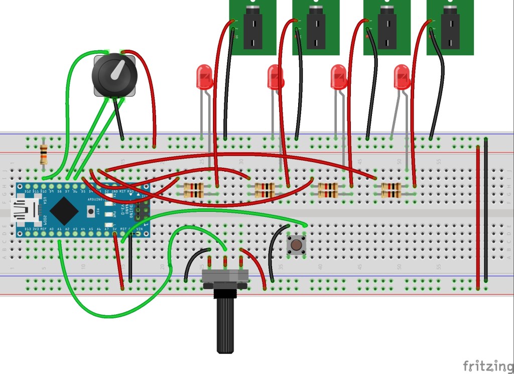
- Place the Arduino on the breadboard bridging the valley.
- Solder single core cable leads to the tip and sleeve connectors of all the mono sockets.
- Solder single core cable leads to all the connectors of the encoder.
- Connect the 10k resistor between D10 and the ground rail of the breadboard.
- Connect one of the push action connectors of the encoder to D10 on the Arduino.
- Connect the other push action connector to the live rail of the breadboard.
- Connect the left-hand connector of the encoder to D7 on the Arduino.
- Connect the middle connector of the encoder to the ground rail of the breadboard.
- Connect the right-hand connector of the encoder to D6 on the Arduino.
- Connect GND on the Arduino to the ground rail of the breadboard.
- Connect 5V on the Arduino to the live rail of the breadboard.
- Connect the left pin of the potentiometer to the ground rail of the breadboard.
- Connect the central pin of the potentiometer to A1 on the Arduino.
- Connect the right pin of the potentiometer to the live rail of the breadboard.
- Connect one of the connectors of the tactile button to the ground rail of the breadboard.
- Connect the other connector of the tactile button to RST on the Arduino.
Now we’ll connect the 4 outputs with their respective LEDs. Repeat the instructions below 4 times, using pins D2, D3, D4 and D5 on the Arduino.
- Connect D(2,3,4,5) on the Arduino to one leg of a 1K resistor.
- Connect the positive (longer) leg of an LED to the other leg of the resistor.
- Connect the negative (shorter) leg of an LED to the ground rail of the breadboard.
- Connect D(2,3,4,5) on the Arduino to another 1K resistor.
- Connect the other leg of the 1K resistor to the tip connector of a jack socket.
- Connect the sleeve connector of the jack socket to the ground rail of the breadboard.
Be aware that once this is up and running, D5 will output the current BPM, D4 will output 1/2 of that, D3 1/4 and D2 1/8.
2. Configure IDE
- On your host computer, go to https://www.arduino.cc/en/main/software and download the correct IDE for your operating system if you don’t already have it.
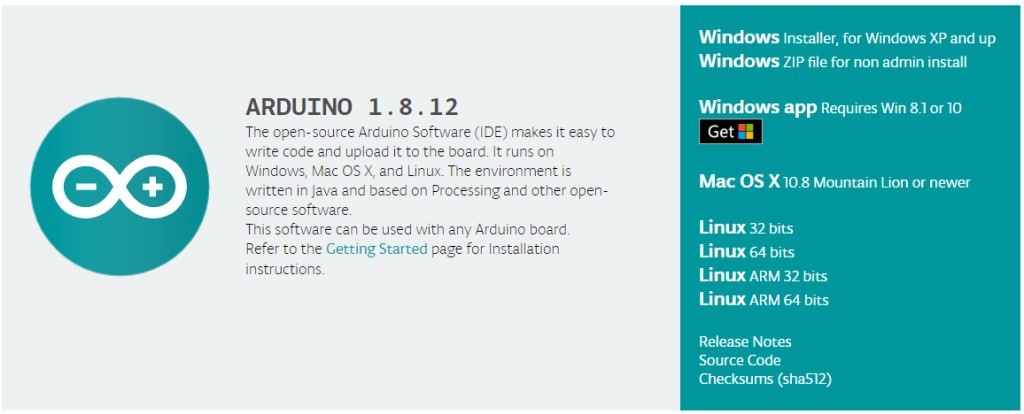
- Once downloaded, install the package by opening it and following any prompts.
- Go to https://github.com/jfturcot/SimpleTimer and download and manually install SimpleTimer.
This is the only SimpleTimer library that will work with this project, do NOT USE the one that you’ll find through the Arduino IDE.
3. Programme the Arduino
- Connect the Arduino to your host computer with the mini USB cable.
- In Arduino IDE, go to Tools>Board and select Arduino Nano.
- In Arduino IDE, go to Tools>Processor and select Atmega328P (Old Bootloader).
- In Arduino IDE, go to Tools>Port and select Atmega328P (Old Bootloader).
- Open a new Arduino sketch and paste the following code:
/*********************This sketch contains parts Programmed by SyntheMafia**********************/
/********************Encoder implementation based on
                   * Copyright 2011 Ben Buxton. Licenced under the GNU GPL Version 3.
                   * Contact: bb@cactii.net
                   * More info: http://www.buxtronix.net/2011/10/rotary-encoders-done-properly.html
                   */
/******************Final implementation by Mowgli***********************************************/


#include <SimpleTimer.h>
SimpleTimer timer;
int count = 0;

int encoderClockPin = 7;
int encoderDataPin = 6;
int encoderCount = 0;

/*************************ENCODER *********************************/


 // Half-step mode?
#define HALF_STEP
// Arduino pins the encoder is attached to. Attach the center to ground.
#define ROTARY_PIN1 7
#define ROTARY_PIN2 6
// define to enable weak pullups.
#define ENABLE_PULLUPS


#ifdef HALF_STEP
// Use the half-step state table (emits a code at 00 and 11)
const char ttable[6][4] = {
  {0x3 , 0x2, 0x1,  0x0}, {0x83, 0x0, 0x1,  0x0},
  {0x43, 0x2, 0x0,  0x0}, {0x3 , 0x5, 0x4,  0x0},
  {0x3 , 0x3, 0x4, 0x40}, {0x3 , 0x5, 0x3, 0x80}
};
#else
// Use the full-step state table (emits a code at 00 only)
const char ttable[7][4] = {
  {0x0, 0x2, 0x4,  0x0}, {0x3, 0x0, 0x1, 0x40},
  {0x3, 0x2, 0x0,  0x0}, {0x3, 0x2, 0x1,  0x0},
  {0x6, 0x0, 0x4,  0x0}, {0x6, 0x5, 0x0, 0x80},
  {0x6, 0x5, 0x4,  0x0},
};
#endif
volatile char state = 0;

/* Call this once in setup(). */
void rotary_init() {
  pinMode(encoderClockPin, INPUT);
  pinMode(encoderDataPin, INPUT);
#ifdef ENABLE_PULLUPS
  digitalWrite(encoderClockPin, HIGH);
  digitalWrite(encoderDataPin, HIGH);
#endif
}

/* Read input pins and process for events. Call this either from a
 * loop or an interrupt (eg pin change or timer).
 *
 * Returns 0 on no event, otherwise 0x80 or 0x40 depending on the direction.
 */
char rotary_process() {
  char pinstate = (digitalRead(encoderDataPin) << 1) | digitalRead(encoderClockPin);
  state = ttable[state & 0xf][pinstate];
  return (state & 0xc0);
}


void setup() {
  Serial.begin(9600);
  rotary_init();


  pinMode(2, OUTPUT);//LED
  pinMode(3, OUTPUT);//LED
  pinMode(4, OUTPUT);//LED
  pinMode(5, OUTPUT);//LED
  pinMode(10, INPUT);//encoder button input
  //pinMode (encoderClockPin,INPUT_PULLUP);
  //pinMode (encoderDataPin,INPUT_PULLUP);
  //pinMode(9, INPUT);//encoder A input
  //pinMode(8, INPUT);//encoder B input


    }

bool started = false;
int priority = 0;
int tapX = 0;
int tapactual;
int tap_time;
int time_actual;
int input1X = 0;
float BPM = 60;

int max_BPM = 500; /******************************************** max BPM that you want */
int min_BPM = 60;  /******************************************** min BPM that you want */
int max_time = ((1/(min_BPM/60)) * 1000);
int min_time = ((1/(max_BPM/60)) * 1000);


void loop() {


 if (!started) {
    cycle_on();
    started = true;
  }

  timer.run();


  //**************ENCODER BUTTON INPUT******************


  if (digitalRead(10) == HIGH && tapX ==0){
    tapX = millis ();
    while (digitalRead (10) == HIGH){
      delay(1);
    }
   }

  if (digitalRead (10) == HIGH && tapX !=0  ){
    tapactual = millis ();
    tap_time = (tapactual - tapX);
    if (tap_time > max_time){
      tap_time = max_time;
    }
     if (tap_time < min_time){
      tap_time = min_time;
    }
    tapX = tapactual;
    priority = 1;
    while (digitalRead (10) == HIGH){
      delay(1);
    }
   }
   time_actual = millis ();
    if ((time_actual - tapX) > 4000){
      tapX = 0;
    }


  //encoder*******************************************

  char result = rotary_process();
  if (result)
    Serial.println(result == 0x40 ? "LEFT" : "RIGHT");

    if (result == 0x40){
    encoderCount = -1;
     }else if (result == 0){
    encoderCount = 0;
     }
     else{encoderCount = 1;}


   BPM = BPM + encoderCount;
 //  Serial.print(" encoder count: ");
 // Serial.println (encoderCount);
Serial.print(" BPM: ");
Serial.println(BPM);

}


void cycle_off() {
  digitalWrite(2, LOW);
  digitalWrite(3, LOW);
  digitalWrite(4, LOW);
  digitalWrite(5, LOW);

  count++;

  if (count == 8) {
    count = 0;
  }
}


void cycle_on() {

  /* duty duration knob*****************************************************************/

  int input2 = analogRead(A1);
  float duration_percentage =  map(input2, 0, 1023, 1, 90);

  int cycletime = (60000/BPM); // works out millisecond gap between beats

  float cycle_start = cycletime;
  float cycle_stop = (cycletime * (duration_percentage/100)); // works out gate length based on percentage of millisecond gap between beats

  Serial.print(" Duration percentage: ");
  Serial.println(duration_percentage);
  Serial.print(" Cycletime: ");
  Serial.println(cycletime);
  Serial.print(" Input2: ");
  Serial.println(input2);

  //**************************************************

  switch (count) {
    case 0:
      digitalWrite(2, HIGH);
      digitalWrite(3, HIGH);
      digitalWrite(4, HIGH);
      digitalWrite(5, HIGH);
      break;

    case 1:
      digitalWrite(2, HIGH);
      break;

    case 2:
      digitalWrite(2, HIGH);
      digitalWrite(3, HIGH);
      break;

    case 3:
      digitalWrite(2, HIGH);
      break;

    case 4:
      digitalWrite(2, HIGH);
      digitalWrite(3, HIGH);
      digitalWrite(4, HIGH);
      break;

    case 5:
      digitalWrite(2, HIGH);
      break;

    case 6:
      digitalWrite(2, HIGH);
      digitalWrite(3, HIGH);
      break;

    case 7:
      digitalWrite(2, HIGH);
      break;
  }


  if (priority == 1){
     BPM = (60000 / tap_time);


  }

  timer.setTimeout(cycle_start, cycle_on);
  timer.setTimeout(cycle_stop, cycle_off);

}

/*********************************************************************/- Load the sketch to your Arduino by pressing on the right-pointing arrow.
That’s it! Your clock should now be cycling through the LEDs and outputting clock signals through the jack sockets. You can change the tempo by tapping a beat on the encoder’s push action, you can also use the encoder’s rotation to slow down and speed up the tempo. You can adjust the duration of the signal using the potentiometer. The button will reset the Arduino, you won’t need this while your project is breadboarded but it will be useful if you decide to finalise the clock and put it in an enclosure.
4. Do more
Now that you now have the clock up and running you can dive deeper into the code and tweak it to your liking. You can start by changing the maximum and minimum BPM or the default BPM which is set to 60.
You could easily turn it into a Eurorack module by incorporating the appropriate power connections. Alternatively, you could make an enclosure for it and include battery power or simply power it through USB.
Like what you read? Why not show your appreciation by giving some love.
From a quick tap to smashing that love button and show how much you enjoyed this project.

