Turning on an LED is one of the first projects you do with Arduino, but turning on your Christmas lights is much more fun, especially if you can do it as if by magic when you walk into the room!
There are lots of ways to do this, like PIR or sonar sensors but these detect anyone. This project uses Bluetooth Low Energy (BLE) signals on your phone to trigger a relay that will switch on your Christmas decorations, or anything else for that matter.
In the project, you will learn about BLE scanning, what it is and how it can be used to estimate proximity using signal strength, as in the NHS COVID-19 app. It will also show you how to safely switch higher powered electrical equipment using Arduino and how to debounce a switching signal that fluctuates. All extremely useful things for your future projects and it’s not that difficult when you know-how.
Here’s the project in action:
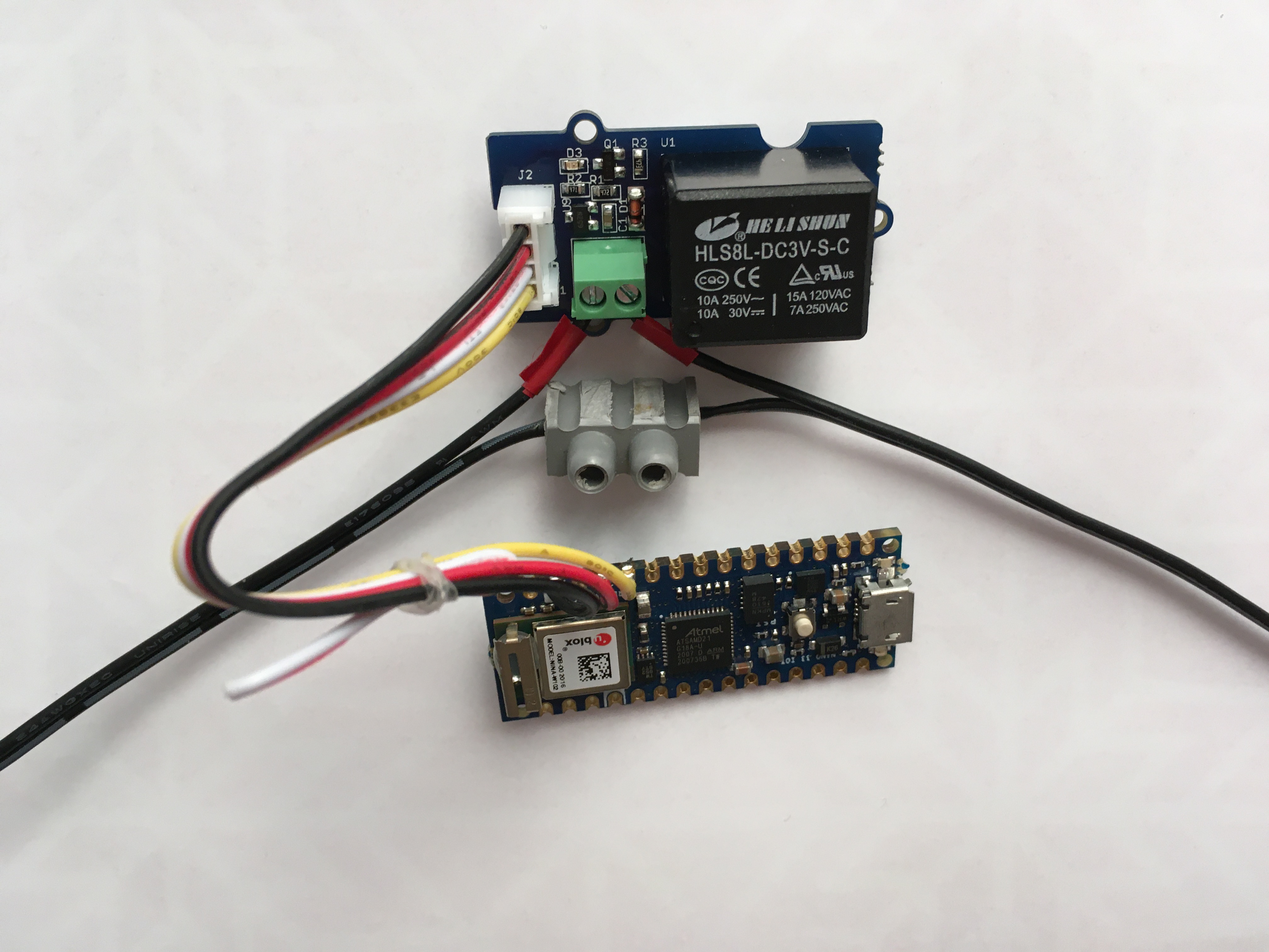
1. Build the circuit
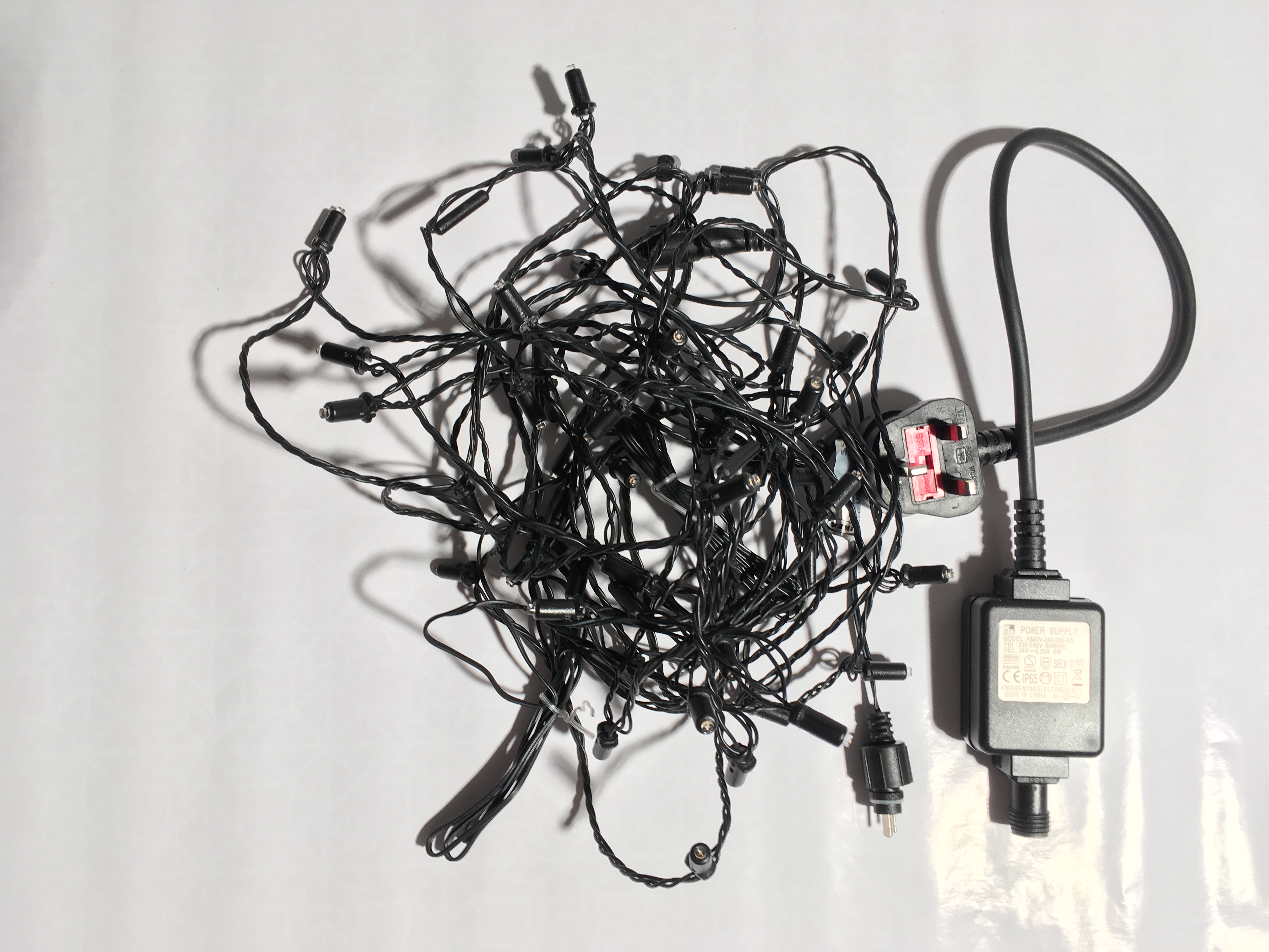
We are going to be using an Arduino Nano 33 IoT to switch on a set of LED Christmas lights. These should be the type that has a built-in low voltage AC/DC transformer for safety.
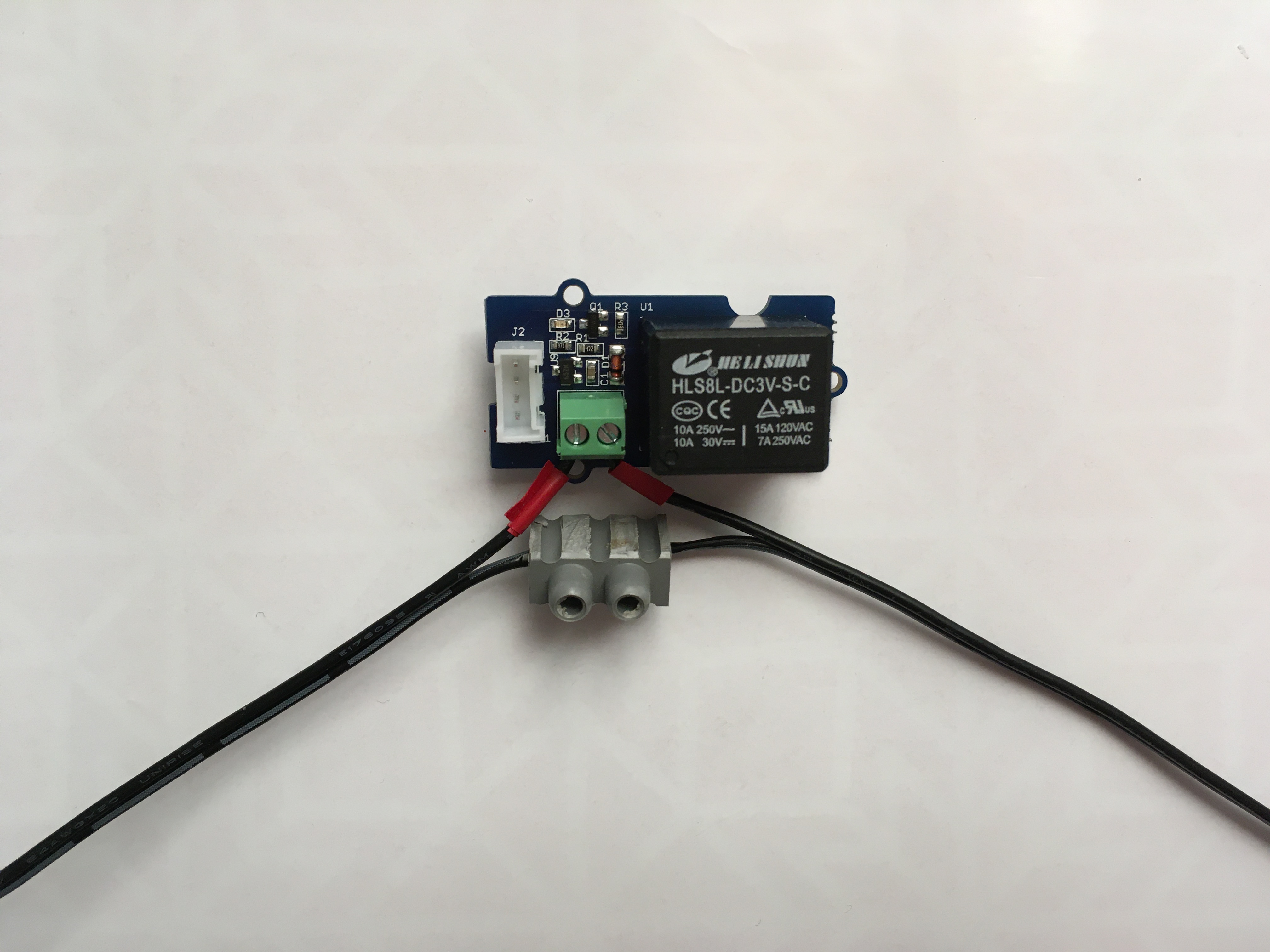
One of the easiest ways to switch a DC load is using a relay. The Grove Relay Module has all the required circuitry needed to connect it safely and easily to an Arduino without damaging it. Before connecting the relay, it is important to consider its maximum ratings.
The lights we used are from IKEA rated for 24VDC at 0.25A (6W) – the relay module has a max switching voltage of 30VDC and a max switching current of 5A so these lights are well within its rating.
Only use low voltage DC LED’s. Using more than 24V can be dangerous.
We will connect the low voltage cable coming from the transformer to the relay module so that the positive line is switched by the relay.
- Cut the low voltage cable connected to the lights, strip each wire back about 3mm and tin the ends with solder.
- Test the polarity of the wires coming from the transformer with a multimeter and identify the positive and ground leads. The ground lead on our lights was marked with a dash to distinguish it from the positive lead. We marked the positive lead with red tape to make it easily visible.
- Connect the positive lead from the transformer to one of the screw terminals on the Relay Module.
- Connect the positive lead connecting the lights to the other screw terminal of the Relay Module. The order is not important.
- Connect the ground lead from the transformer to the ground lead connected to the lights with a screw terminal.
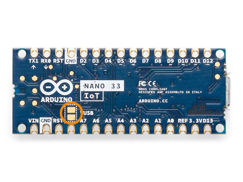
When the Nano 33 IoT is powered from the USB connector, the input voltage (5V) is available on the pin marked VUSB if the solder bridge on the bottom of the board is connected.
Arduino publish the schematics for their boards in PDF format in the documentation section of the product pages so you can inspect them.
The Grove Relay Module V1.2 needs a VCC of 5V to operate and draws 100mA. It has a transistor connected to the signal line (SIG) so it’s safe to connect to the 3.3V pins on the Arduino.
- Cut the connector cable supplied with the relay module in half, strip the cable ends back 2mm and tin with solder.
- Solder the black (GND) lead to the GND pin on the Arduino.
- Solder the red (VCC) lead to the +5V pin on the Arduino.
- Solder the yellow (SIG) lead to pin A7 (D21) on the Arduino.
- The white lead is not connected.
- Solder the VUSB bridge on the underside of the Arduino.
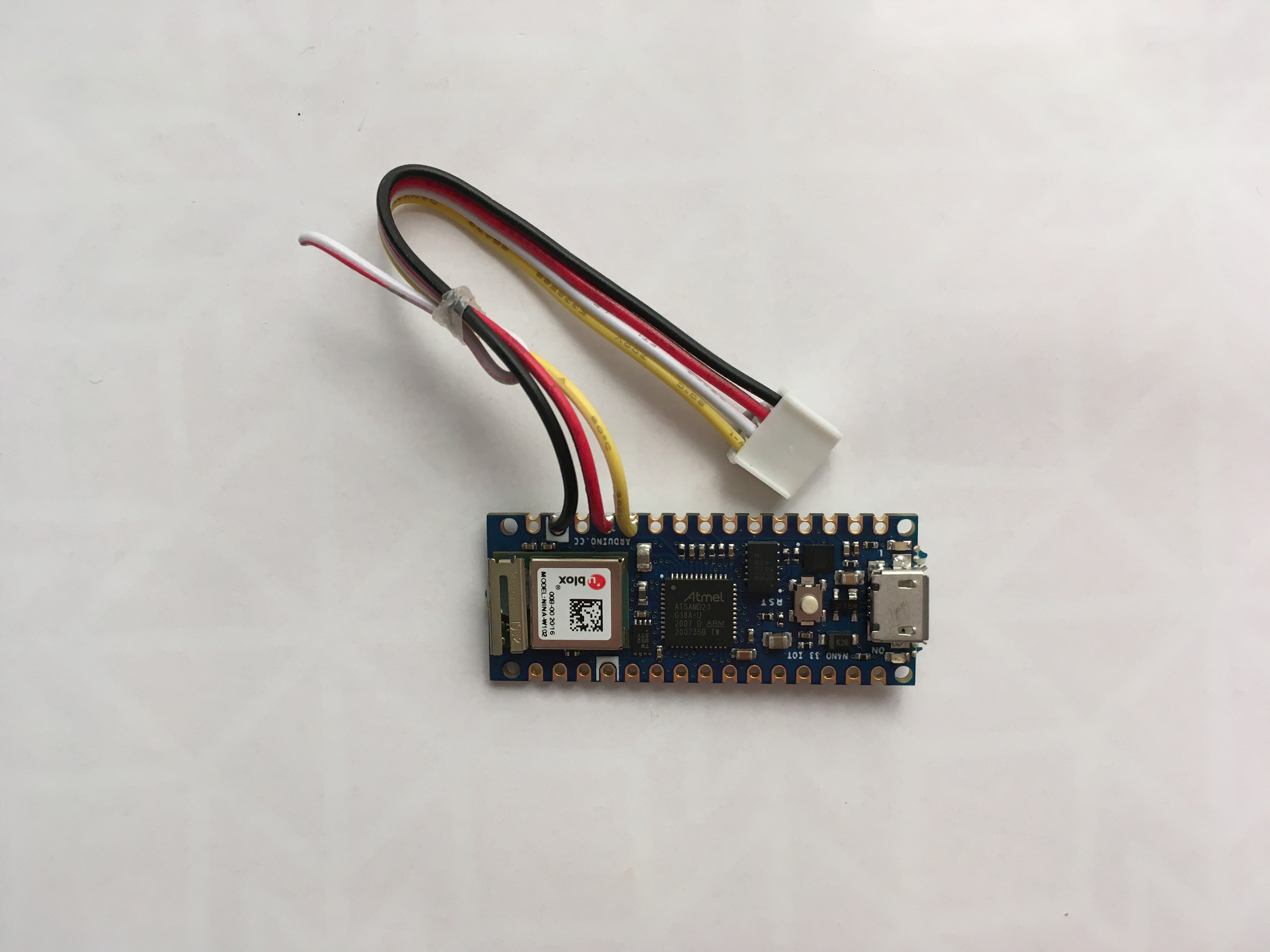
- Plug the connector cable into the relay module to complete the hardware setup.
2. Download software
The software that runs on the Arduino is available on the OKdo GitHub.
- Download the code from GitHub in ZIP format by selecting the Code dropdown:
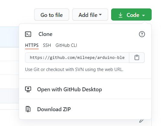
- Expand the zip file to a directory on your PC.
- Navigate to the ArduinoBLESwitchMode.ino file and open it in the Arduino IDE.
- Make sure that the Arduino BLE library is installed.
More information about how to do this is in the Get Started guide.
3. Arduino code
This section looks at how the code running on the Arduino uses BLE signals from your phone to activate the relay module and switch the lights on and off.
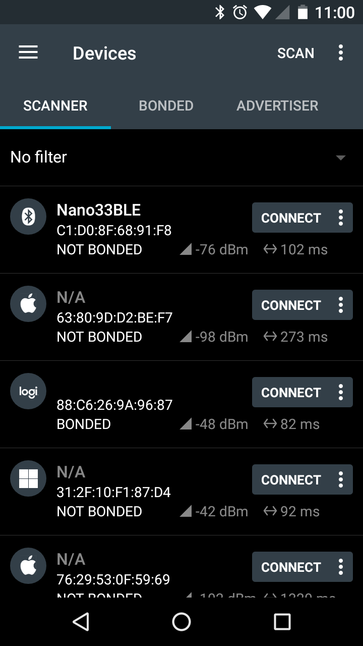
If you scan the area with a BLE app like the nRF Connect for Mobile (available from your app store), you will probably see several BLE devices advertising their presence. Each device broadcasts a unique identifier (24-bit MAC address), whether it’s connectable and any services it provides.
BLE services have a unique identifier or UUID which are standardised by the Bluetooth SIG https://www.bluetooth.com
The receiving device can calculate the received signal strength (RSSI) which can be used to estimate proximity of the device being scanned.
In Bluetooth terminology, the Arduino will act as a GAP Observer and the phone as a GAP Peripheral. The Arduino will constantly scan for any peripherals close by, based on a service UUID. It won’t connect to the peripheral, it will only calculate its proximity based on the RSSI value so that when the phone is close enough, it will switch the relay on. If the phone moves away, it will switch the relay off.
Many of us in the UK have the NHS COVID19 app installed on our phones. This advertises the Exposure Service with UUID “FD6F” so it was used for testing. You can install any BLE peripheral app and use that if you prefer.
You can find out more about how Bluetooth is being used to fight COVID here.
Code listing
At the top, the code imports the Arduino BLE library which provides the C++ classes for interacting with BLE devices. The library is documented here https://www.arduino.cc/en/Reference/ArduinoBLE
#include <ArduinoBLE.h>Several constants are declared to configure the scan behaviour; MIN_RSSI sets the minimum signal strength that will flip the switch. Altering this to a higher value means the phone must be closer to activate the switch and further away if you lower it.
const int MIN_RSSI = -85;Signal strength varies constantly so a strategy in needed to stabilise (debounce) it so it can be compared to the fixed switching value above. The statistical mode of the RSSI was chosen, so several scans are required to calculate this. This is set by this constant below and affects the reaction speed of the switch:
const int RSSI_COUNT = 4;A timeout value in milliseconds is used by the scanning function if the phone suddenly goes out of range.
In the setup function and before scanning can take place, a callback Event Handler is set. This handler is triggered each time a peripheral is discovered, and it sets the Callback Function. It’s in this function that the switching logic takes place.
Following that, a scan is started. The scanForUuid function filters based on service UUID. Duplicate scans are set to true so that the scanned device can appear in each scan, allowing the mode calculation.
  BLE.setEventHandler(BLEDiscovered, bleDiscoveredHandler);
  BLE.scanForUuid(UUID, true);   // Scan with duplicates
The main loop is sparse, it just polls constantly and times out if the discovered callback doesn’t return. This stops the code from blocking if the phone suddenly goes out of range.
BLE.poll(TIMEOUT);Inside the discovered callback, each time a scan finds a peripheral, the RSSI value is stored in an array, ready for the mode calculation.
  int rssi = peripheral.rssi();
  if (count < RSSI_COUNT) {
    rssiArray[count++] = rssi;
    return;
  }
When enough RSSI values are captured, the statistical mode is calculated, and the result compared with the threshold value. This determines if the phone is in, or out of range and stops the switch changing every time the signal strength fluctuates.
 int modeRSSI = mode(rssiArray, RSSI_COUNT);
  range_now = modeRSSI > MIN_RSSI ? IN_RANGE : OUT_OF_RANGE;
The switching logic then kicks in and if the state changes, the action function switches the switch pin high or low accordingly. It’s this pin that is connected to the relay.
  if (range_now != range_before) {
    range_before = range_now;
    if (range_now == IN_RANGE) {
      Serial.println(" Turning ON");
      action(IN_RANGE);
    }
…
Then another scan starts. Each scan takes only a few milliseconds.
4. Testing
When the code has been uploaded to the Arduino, keep it attached to your PC for testing and tuning. This is easier if you have a laptop so you can put the Arduino and relay in its final position.
Open the IDE’s Serial Monitor to view the debug output including MAC address, RSSI value and range condition for each scan. This output can help you tune the constants in the code.
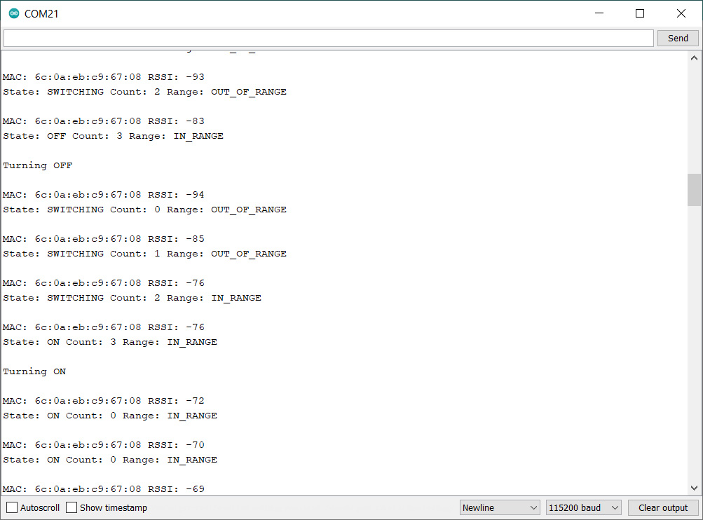
You should now be able to switch the lights on and off by moving your phone in or out of range. Adjust the minimum RSSI value until it works the way you want it for your environment. Any changes must be saved and uploaded to the Arduino.
Once everything is set up and working, disconnect the USB cable from your PC and plug in the power supply so the system runs independently.
Summary
Being able to switch higher power items on and off with an Arduino is extremely useful in lots of applications. With more and more BLE devices becoming common place, an understanding of how they work allows you to investigate them and start to build the technology in to future projects.
To the amazement of onlookers, you should be able to turn on your Christmas lights by entering the room with your mobile, and if you wave your hands in front of you it will seem like magic.
Happy BLE switching!
Like what you read? Why not show your appreciation by giving some love.
From a quick tap to smashing that love button and show how much you enjoyed this project.

