
If you followed our Raspberry Pi Pico MicroPython getting started guide you should have your PC, Raspberry Pi 4B or Pi 400 setup for programming the Pico in MicroPython.
The Pico has 26 multi-function General Purpose I/O (GPIO) pins, 3 of which can be configured as Analogue to Digital Converter (ADC) inputs. These are capable of measuring the analogue output signals that many sensors and add-on devices use.
This guide will take you through three examples showing how to connect and read analogue devices and use their input to control digital outputs in MicroPython.
What you'll need
2.54mm male headers
Breadboard
1 LED
10k Ohm potentiometer
220 Ohm resistor
BS270 N-channel MOSFET
HDMI monitor
Internet connection
Build the circuit
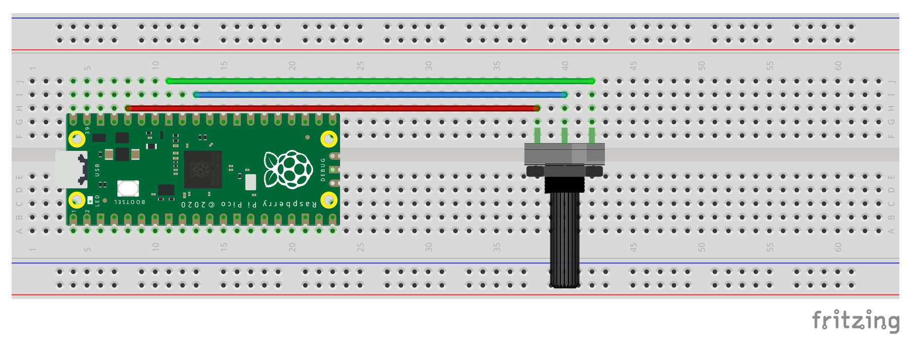
All three examples use the same basic circuit, with the Pico connected to your PC, a Raspberry Pi 4B or Pi 400 using a microUSB cable for power and programming.
To keep things simple, the analogue input will come from the central terminal of a 10k Potentiometer connected across the Pico’s 3.3V output and ground so it acts as a variable voltage divider. Any 10 – 50k Ohm potentiometer would be suitable.
It is important not to exceed the 3.3V maximum for the ADC input or any GPIO pin
Make sure the Raspberry Pi is powered down and the power supply removed before making any connections, then check them carefully before powering on.
| Potentiometer | Pico | Colour |
| Power | 3.3V OUT (PIn 36) | Red |
| Ground | GND (Pin 33) | Green |
| Center | ADCO (PIN 31) | Blue |
Read analogue input
The Pico has a single 12-bit resolution, 4-channel ADC with a 3.3V internal reference and available inputs on 0-3 (GPIO 26-29), the internal chip temperature sensor is on input 4.
This means you can measure input voltages between 0V and 3.3V (Maximum) at a resolution of 0.81mV (3.3 / 4095) although in MicroPython this is scaled to 16-bit value from 0 to 65535.
In the first example (adc_read.c) the voltage across the potentiometer is read as a raw ADC input which is a value between 0 and 65535. This is converted to a voltage value using the conversion factor for the Pico ADC before being printed to the output.
Adjusting the potentiometer will change the raw value from a minimum of 0 to a maximum of 65535 and the voltage from 0V to 3.3V approximately.
The full code listing is shown below. It imports the ADC and Pin modules necessary for controlling these peripherals, then initialises GPIO 26 as an ADC input on channel 0 before reading the potentiometer value every second. The raw value is converted to a voltage and both are output to the shell.
 from machine import ADC, Pin
 from utime import sleep
 pot = ADC(26)
 conversion_factor = 3.3 / 65535


 while True:
     raw = pot.read_u16()
     volts = raw * conversion_factor
     print('Raw: {} '.format(raw), 'Voltage {:.1f}V'.format(volts))
     sleep(1)
To run the code example in Thonny clone the samples from the OKdo Github:
 cd ~/pico
 git clone https://github.com/LetsOKdo/pico-basics-py.git
Load into Thonny:
- Install MycroPython bootloader http://www.raspberrypi.org/documentation/rp2040/getting-started/
- Open Thonny and set interpreter to MicroPython (Raspberry Pi Pico).
- Load example code eg. File > pi/pico/pico-basics-py/pico_io/adc_read.py
- Run script – Run > Run current script (F5).
- Stop script – Run > Stop/Restart backend (Ctrl+F2).
View the output in the Thonny Shell.
Analogue input & digital output
The next example (adc_read_blink) uses the same circuit but this time the potentiometer’s raw value is mapped to a time delay that can be used to flash the on-board output LED. When the potentiometer is altered the blink rate varies accordingly.
The full code listing is below. The onboard LED (GPIO 25) is defined followed by a mapping function that transforms the raw ADC reading into a value between 0 and 1 second to alter the LED blink rate. As well as setting up the ADC input, a GPIO output must be set to the onboard LED. Then in the loop, the ADC value is read, tested to make sure it’s in bounds of the map function then it’s transformed to the delay value.
 from machine import ADC, Pin
 from utime import sleep


 pot = ADC(26)
 led = Pin(25, Pin.OUT)


 def map(s, a1, a2, b1, b2):
     return b1 + (s - a1) * (b2 - b1) / (a2 - a1)


 while True:
     raw = pot.read_u16()
     delay = map(raw, 0, 65535, 0, 1)
     print('Raw: {} '.format(raw), 'Delay {:.1f}s'.format(delay))
     led.value(1)
     sleep(delay)
     led.value(0)
     sleep(delay)
Run the code in Thonny by opening the Python script as in the previous example.
Multi-core
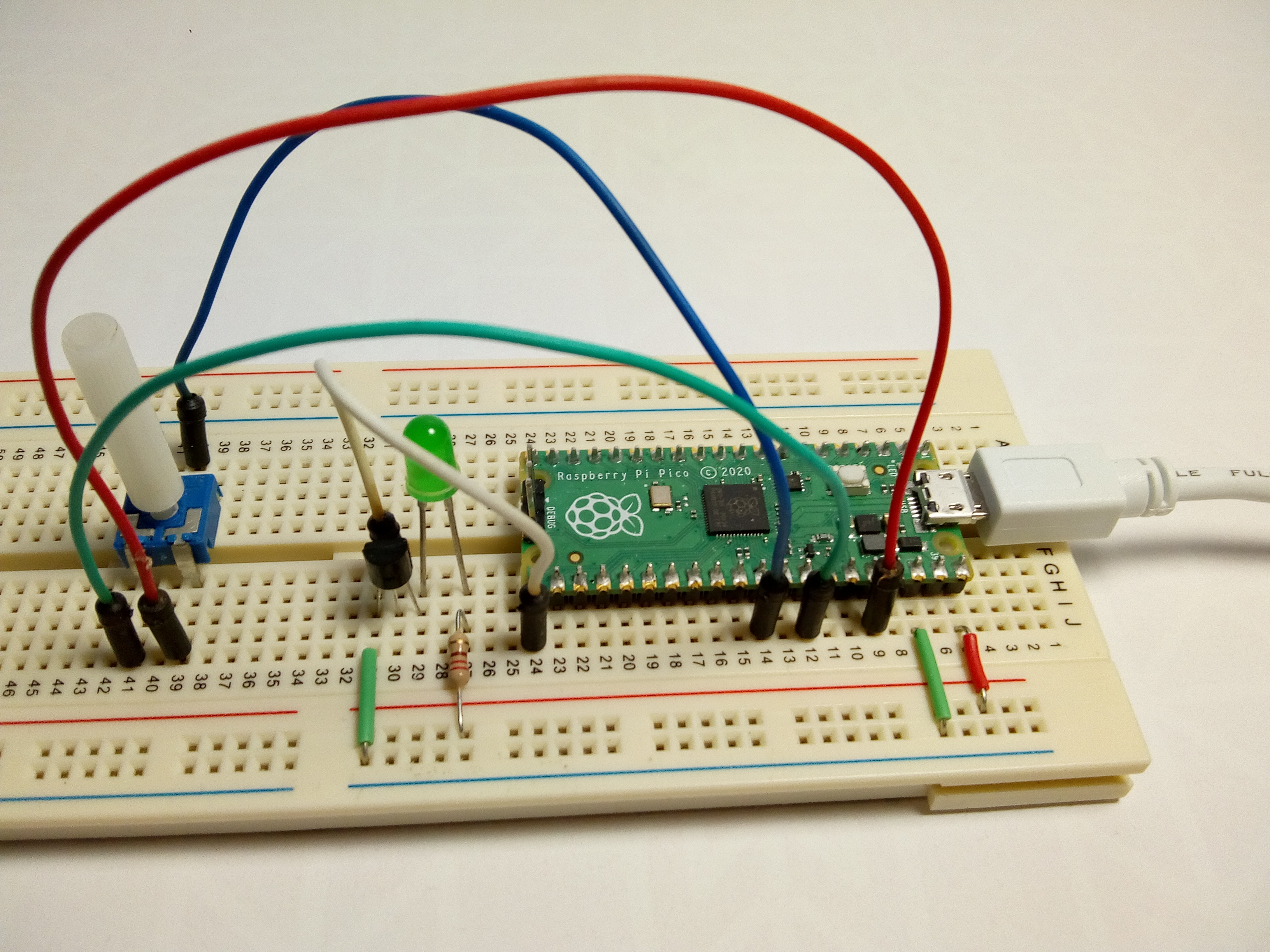
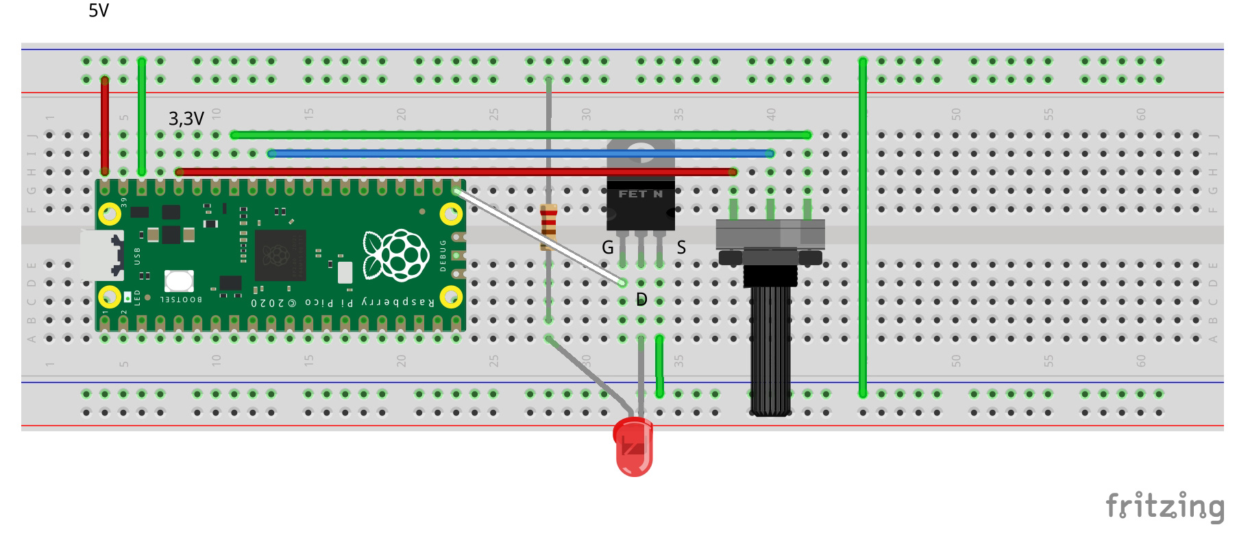
The last example (adc_read_multi) demonstrates reading the ADC input using Core 0 to drive an output on Core 1. An external LED is added to the circuit showing how to connect a device with a voltage greater than the 3.3V maximum for the GPIO pins.
Add an LED, 220 Ohm resistor and N-channel MOSFET (BS270 is suitable) to the circuit as shown below with the power disconnected.
Make sure to check your MOSFET pin configuration as they are not standardised.
| MOSFET | Connection | Colour |
| Drain (D) | LED cathode | |
| Gate (G) | Pico GPIO 16 (PIn 21) | White |
| Source (S) | GND |
The LED is connected via a current limiting resistor to the Pico VBUS which is at 5V. This is high enough to damage the GPIO pins if they are connected directly. The MOSFET acts as a switch allowing current to flow across the Drain to Source when the Gate to Source voltage rises above a threshold value. Because the GPIO output is not connected to the higher voltage it is protected.
The code listing is below. The ADC input and the GPIO output that switches the MOSFET and LED is set up. The final while loop runs on Core 0 and reads the ADC and maps the raw value as before, but this time a global variable is updated that can be accessed by both cores.
A function is defined (core1_blink) to flash the LED which runs on Core 1. This is started by calling the start_new_thread function and passing a reference to the task to be run in the thread.
A short delay is added after Core 1 launches to allow time for it to start up. Without this you may get all kinds of strange errors.
Now when the potentiometer value changes, the LED delay is updated on the other core. This is a very simple way of sharing a variable value across the cores where synchronisation is not required.
 from machine import ADC, Pin
 from utime import sleep
 import _thread


 pot = ADC(26)
 led = Pin(16, Pin.OUT)


 delay = 1


 def core1_task():
     global delay
     while True:
         led.value(1)
         sleep(delay)
         led.value(0)
         sleep(delay)


 def map(s, a1, a2, b1, b2):
     return b1 + (s - a1) * (b2 - b1) / (a2 - a1)


 _thread.start_new_thread(core1_task, ())


 sleep(1) # wait for core1 to start


 while True:
     raw = pot.read_u16()
     delay = map(raw, 0, 65535, 0, 1)
     print('Raw: {} '.format(raw), 'Delay {:.1f}s'.format(delay))
     sleep(0.5)
Load and run the code in Thonny as previously.
Summary
This guide demonstrated how to program the Pico’s analogue inputs and use their values to control digital outputs, on either of the Pico’s cores using MicroPython.
It also showed how to control output devices that run at more than the maximum 3.3V GPIO voltage level using a MOSFET as a switch.
The example code provided can be used as a basis for many different input/output scenarios with analogue sensors and add-on boards and is available on the OKdo Github: https://github.com/LetsOKdo/pico-basics-py
For more information on the Raspberry Pi Pico Python SDK visit: https://datasheets.raspberrypi.org/pico/raspberry-pi-pico-python-sdk.pdf
Further information about the Pico GPIO and ADC can be found in the datasheet.