If you followed our Raspberry Pi Pico Visual Studio getting started guide you should have a working VSCode environment setup on your Raspberry Pi 4B or Pi 400 for programming your Pico in C/C++. You can now get started with Raspberry Pi Pico GPIO and C/C++.
The Pico has 26 multi-function General Purpose I/O (GPIO) pins, 3 of which can be configured as Analogue to Digital Converter (ADC) inputs. These are capable of measuring the analogue output signals that many sensors and add-on devices use.
This guide will take you through three examples showing how to connect and read analogue devices and use their input to control digital outputs using C/C++.
What you'll need
2.54mm male headers
Breadboard
1 LED
10k Ohm potentiometer
220 Ohm resistor
BS270 N-channel MOSFET
HDMI monitor
Internet connection
Build the circuit
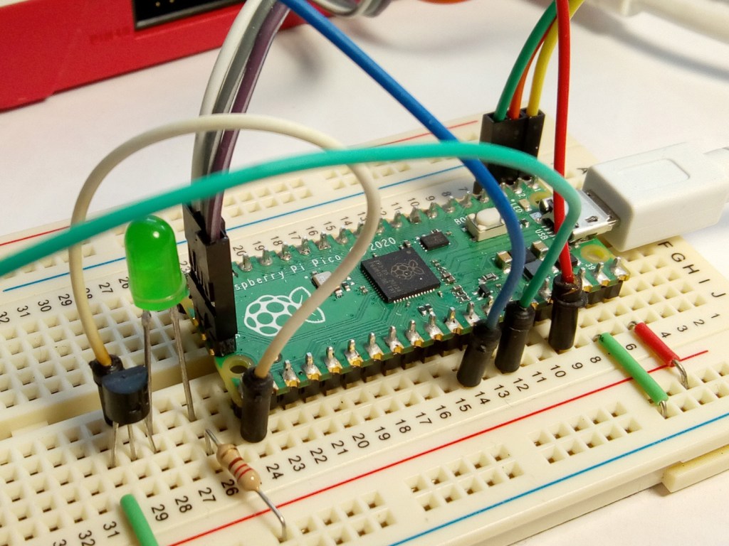
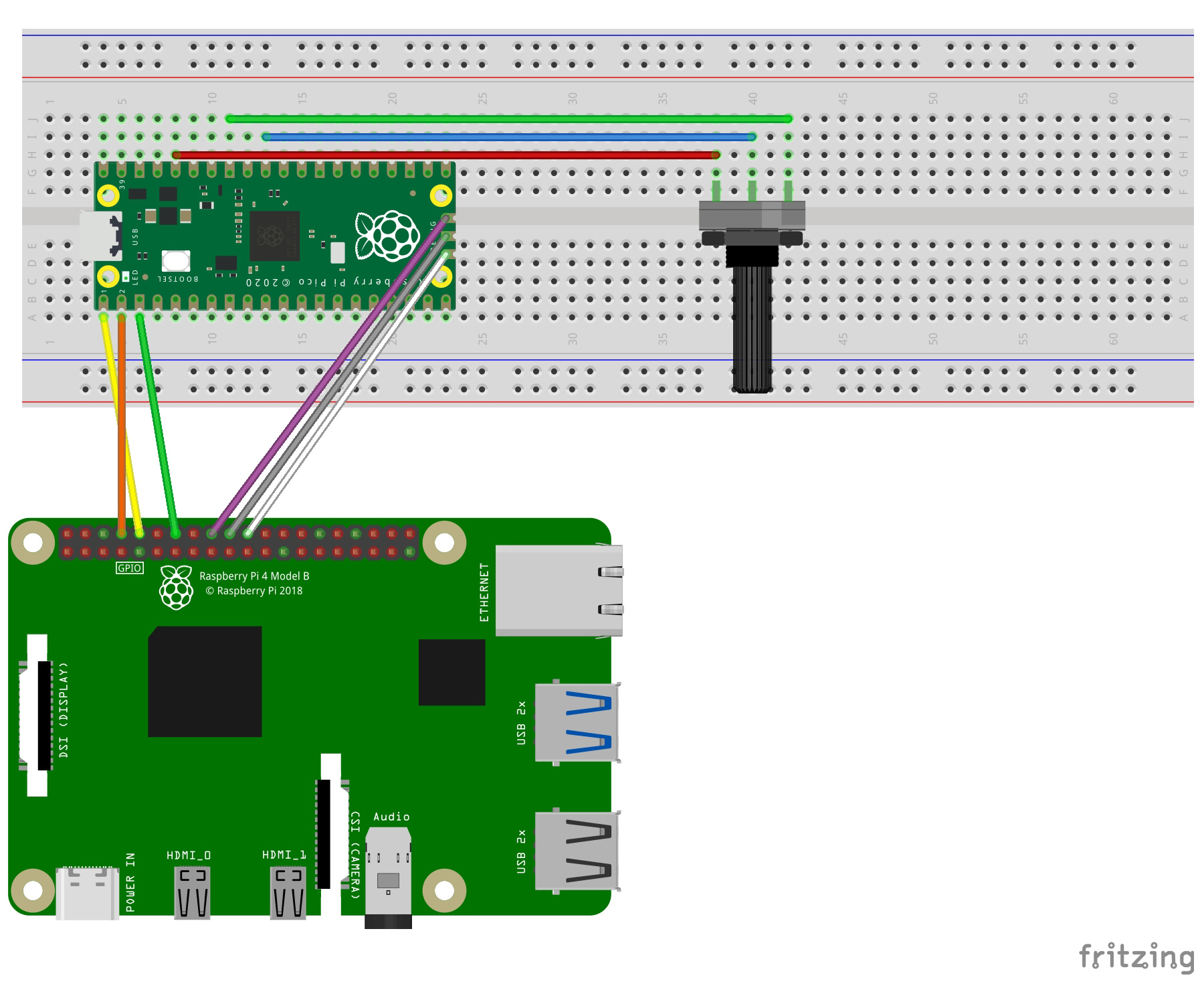
All three examples use the same basic circuit, with the Pico connected to a Raspberry Pi 4B or Pi 400. VSCode supports programming and debugging the Pico via the Serial Wire Debug (SWD) port and output can be viewed via the serial UART.
To keep things simple, the analogue input will come from the central terminal of a 10k potentiometer connected across the Pico’s 3.3V output and ground so it acts as a variable voltage divider. Any 10 – 50k Ohm potentiometer would be suitable.
It is important not to exceed the 3.3V maximum for the ADC input or any GPIO pin
Power the Pico by connecting a microUSB cable to the Pico from the Raspberry Pi.
Make sure the Raspberry Pi is powered down and the power supply removed before making any connections, then check them carefully before powering on.
SWD port connections
| Raspberry Pi | Pico | Colour |
| GPIO24 (Pin 18) | SWDIO | Purple |
| GND (Pin 20) | GND | Grey |
| GPIO25 (Pin 22) | SWCLK | White |
UART connections
| Raspberry Pi | Pico | Colour |
| GPIO14 (UART0_TX, Pin 8) | UART0_RX (Pin 2) | Orange |
| GPIO15 (UART0_RX, Pin 10) | UART0_TX (Pin 1) | Yellow |
| GND (Pin 14) | GND (Pin 3) | Green |
Potentiometer connections
| Potentiometer | Pico | Colour |
| Power | 3.3V OUT (Pin 36) | Red |
| Ground | GND (Pin 33) | Green |
| Center | ADC0 (Pin 31) | Blue |
Read analogue input
The Pico has a single 12-bit resolution, 4-channel ADC with a 3.3V internal reference and available inputs on 0-3 (GPIO 26-29), the internal chip temperature sensor is on input 4.
This means you can measure input voltages between 0V and 3.3V (Maximum) at a resolution of 0.81mV (3.3 / 4095)
In the first example (adc_read.c) the voltage across the potentiometer is read as a raw ADC input which is a 16-bit unsigned integer value between 0 and 0xFFF (4095). This is converted to a voltage value using the conversion factor for the Pico ADC before being printed to the output.
Adjusting the potentiometer will change the raw value from a minimum of 0x0 to a maximum of 0xFFF and the voltage from 0V to 3.3V approximately.
To use the ADC functions, the hardware/adc.h header must be included in the .c source file and an entry must also be added to CMakeLists.txt:
 # Add the standard library and hardware adc to the build
 target_link_libraries(adc_read pico_stdlib hardware_adc)
The full code listing is shown below. It initialises GPIO 26 as an ADC input on channel 0 then reads the potentiometer value every second. The raw value is converted to a voltage and both are output on the serial UART.
adc_read.c
 #include <stdio.h>
 #include "pico/stdlib.h"
 #include "hardware/adc.h"


 const uint delay = 1000; // 1s delay


 int main() {
     stdio_init_all();
     printf("ADC Example, measuring GPIO26\n");


     adc_init();
     adc_gpio_init(26);
     adc_select_input(0);


     while (1) {
         // 12-bit conversion, assume max value == ADC_VREF == 3.3 V
         const float conversion_factor = 3.3f / (1 << 12);
         uint16_t result = adc_read();
         printf("Raw value: 0x%03x, voltage: %f V\n", result, result * conversion_factor);
         sleep_ms(delay);
     }
 }
To run the code example in VSCode clone the samples from the OKdo Github: https://github.com/LetsOKdo/pico-basics-c
 cd ~/pico
 git clone https://github.com/LetsOKdo/pico-basics-c.git
Load into VSCode
- Open VSCode.
- Open Folder – File -> Open Folder -> pi/pico/pico-basics-c/pico_io
- Set compiler to arm-none-eabi in blue window border.
- Set CMake to debug in blue window border.
Run / Debug example code
- Click Debug icon in LH ribbon bar.
- Click Cortex Debug button in Debug pane.
- Select example target to run from drop-down.
- Click Continue (F5) debug button in main pane.
- Click Stop (Shift + F5) debug button to stop.
Open a minicom session by selecting the Terminal tab and running the following command:
minicom -b 115200 -D /dev/serial0 Analogue input & digital output
The next example (adc_read_blink) uses the same circuit but this time the potentiometer’s raw value will be mapped to a time delay that can be used to flash the on-board output LED. When the potentiometer is altered the blink rate will vary accordingly.
The full code listing is below. The on-board LED (GPIO 25) is defined followed by a mapping function that transforms a raw ADC reading into a value between 0 and 1000ms to alter the LED blink rate. As well as setting up the ADC input, a GPIO output must be set to the on-board LED. Then in the loop the ADC value is read, tested to make sure it’s in bounds of the map function then its transformed to to the delay value.
read_adc_blink.c
 p.p1 {margin: 0.0px 0.0px 8.0px 0.0px; font: 9.0px 'Courier New'; color: #000000; background-color: #878787} p.p2 {margin: 0.0px 0.0px 8.0px 0.0px; font: 9.0px 'Courier New'; color: #000000; background-color: #878787; min-height: 10.0px}
 #include <stdio.h>
 #include "pico/stdlib.h"
 #include "hardware/adc.h"


 #define LED_PIN PICO_DEFAULT_LED_PIN


 int map(int s, int a1, int a2, int b1, int b2) {
   return b1 + (s - a1) * (b2 - b1) / (a2 - a1);
 }


 uint main() {
     stdio_init_all();
     printf("ADC Example, measuring GPIO26 and mapping to blink delay\n");


     adc_init();
     adc_gpio_init(26);
     adc_select_input(0);
     gpio_init(LED_PIN);
     gpio_set_dir(LED_PIN, GPIO_OUT);


     while (1) {
         uint16_t result = adc_read();
         int delay = 0;
         if (result >= 0 && result <= 0xfff)
           delay = map(result, 0, 0xfff, 0, 1000);
         printf("Raw value: 0x%03x, Delay: %u ms\n", result, delay);
         gpio_put(LED_PIN, 1);
         sleep_ms(delay);
         gpio_put(LED_PIN, 0);
         sleep_ms(delay);
     }
 }
Run the code in VSCode by changing the Target by clicking the target name in the blue bottom window border. The output can be viewed in the Terminal pane using minicom.
Multi-core
The last example (adc_read_multi) demonstrates reading the ADC input using Core 0 to drive an output on Core 1. An external LED is added to the circuit demonstrating how to connect a device with a voltage greater than the 3.3V maximum for the GPIO pins.
Add an LED, 220 Ohm resistor and N-channel MOSFET (BS270 is suitable) to the circuit as shown below with the power disconnected.
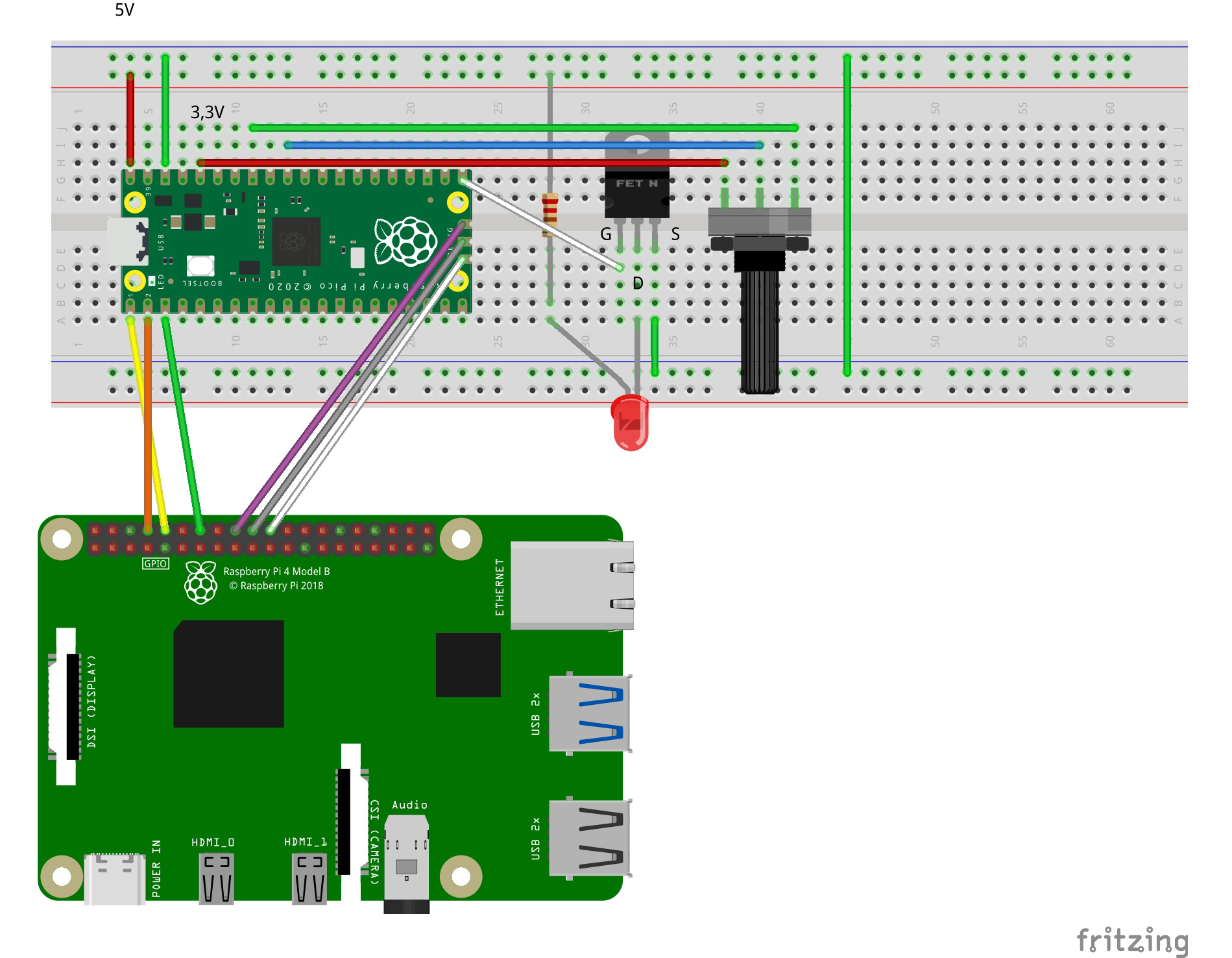
Make sure to check your MOSFET pin configuration as they are not standardised.
| MOSFET | Connection | Colour |
| Drain (D) | LED cathode | |
| Gate (G) | Pico GPIO 16 (Pin 21) | White |
| Source (S) | GND |
The LED is connected via a current limiting resistor to the Pico VBUS which is at 5V. This is high enough to damage the GPIO pins if they are connected directly. The MOSFET acts as a switch allowing current to flow across the Drain to Source when the Gate to Source voltage rises above a threshold value. Because the GPIO output is not connected to the higher voltage it is protected.
The code listing is below. To use multi core functions, the pico/multicore.h header must be included in the .c source file as well as an entry in CMakeLists.txt:
# Add the standard library, multicore and hardware adc to the build
 target_link_libraries(adc_read_multi pico_stdlib pico_multicore hardware_adc)
The ADC input and GPIO output to switch the MOSFET and LED are set up in the main function which runs on Core 0. This reads the ADC and maps the raw value as before but this time a static variable is updated that can be accessed by both cores.
A function is defined (core1_blink) to flash the LED which runs on Core 1. This is started up by calling the multicore_launch_core1 function in main.
Now when the potentiometer value changes, the LED delay is updated on the other core. This is a very simple way of sharing a variable value across the cores where synchronisation is not required.
 p.p1 {margin: 0.0px 0.0px 8.0px 0.0px; font: 9.0px 'Courier New'; color: #000000; background-color: #878787} p.p2 {margin: 0.0px 0.0px 8.0px 0.0px; font: 9.0px 'Courier New'; color: #000000; background-color: #878787; min-height: 10.0px}
 #include <stdio.h>
 #include "pico/stdlib.h"
 #include "pico/multicore.h"
 #include "hardware/adc.h"


 #define LED_PIN 16


 static int delay = 0;


 int map(int s, int a1, int a2, int b1, int b2) {
   return b1 + (s - a1) * (b2 - b1) / (a2 - a1);
 }


 void core1_blink() {
     while (1) {
         gpio_put(LED_PIN, 1);
         sleep_ms(delay);
         gpio_put(LED_PIN, 0);
         sleep_ms(delay);
     }
 }


 void main() {
     adc_init();
     adc_gpio_init(26);
     adc_select_input(0);
     gpio_init(LED_PIN);
     gpio_set_dir(LED_PIN, GPIO_OUT);


     multicore_launch_core1(core1_blink);


     while (1) {
         uint16_t result = adc_read();
         if (result >= 0 && result <= 0xfff)
           delay = map(result, 0, 0xfff, 0, 1000);
         sleep_ms(200);
     }
 }
Run the code in VSCode by changing the Target by clicking the target name in the blue bottom window border. There is no serial output.
Summary
This guide demonstrated how to program the Pico’s analogue inputs and use their values to control digital outputs, on either of the Pico’s cores in C/C++.
It also showed how to control output devices that run at more than the maximum 3.3V GPIO voltage level using a MOSFET as a switch.
The example code provided can be used as a basis for many different input/output scenarios with analogue sensors and add-on boards and is available on the OKdo Github: https://github.com/LetsOKdo/pico-basics-c
For more information on the Raspberry Pi Pico C/C++ SDK see the sdk datasheet.
Further information about the Pico GPIO and ADC can be found in the datasheet.