
- Step 1: Bootloader Firmware Update
- Step 2: Downloading the OpenMV IDE
- Step 3: Nicla Vision LED Codes
- Step 4: Connecting to the OpenMV IDE
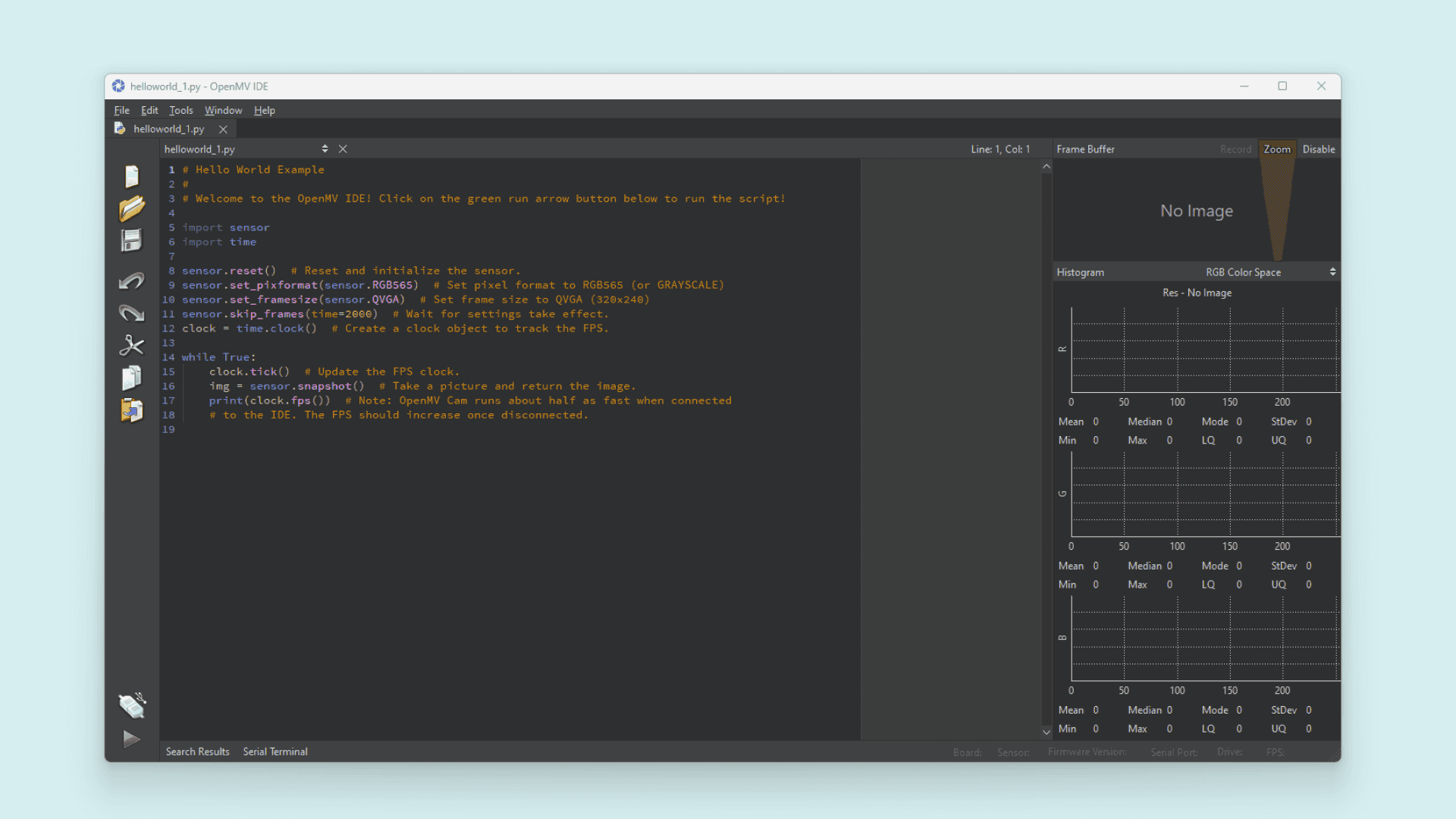
- Step 5: Preparing the Script
- Step 6: Creating the Main Loop in the Script
- Step 7: Uploading the Script
- Step 8: Using the Nicla Vision Camera
- Step 9: Using the Nicla Vision with Arduino IDE (Optional)
- Summary
- Troubleshooting
Learn how to harness the computer vision capabilities of Arduino Nicla Vision with this tutorial using the OpenMV IDE and MicroPython.
With step-by-step instructions, this tutorial guides you through downloading the OpenMV IDE, updating firmware, connecting the Nicla Vision, and writing your first MicroPython script. It covers everything from bootloader firmware updates to script creation and execution. By the end of this tutorial, you’ll have a solid foundation in using Arduino Nicla Vision for computer vision applications. You’ll be equipped with the knowledge to create scripts for LED control, image capture, and more, empowering you to explore the full potential of Arduino Nicla Vision in your projects.
Author: Benjamin Dannegård & Christopher Méndez
Difficulty:
Easy
Time:
2 hours
Steps:
9
Parts Needed to Get Started with Arduino Nicla Vision:
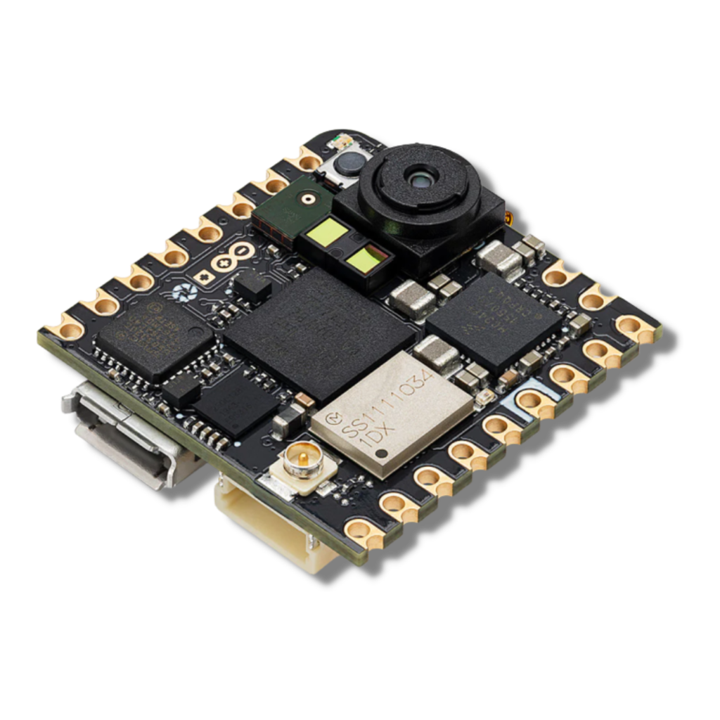
Arduino Nicla Vision
Step 1: Bootloader Firmware Update
To update the bootloader firmware of your product, follow these steps:
- Download the latest version of the board support package by searching for Arduino Mbed OS Nicla Boards in the Arduino IDE’s Boards Manager.

- Next, navigate to File > Examples > STM32H747_System > STM32H747_manageBootloader and upload this sketch to your board.
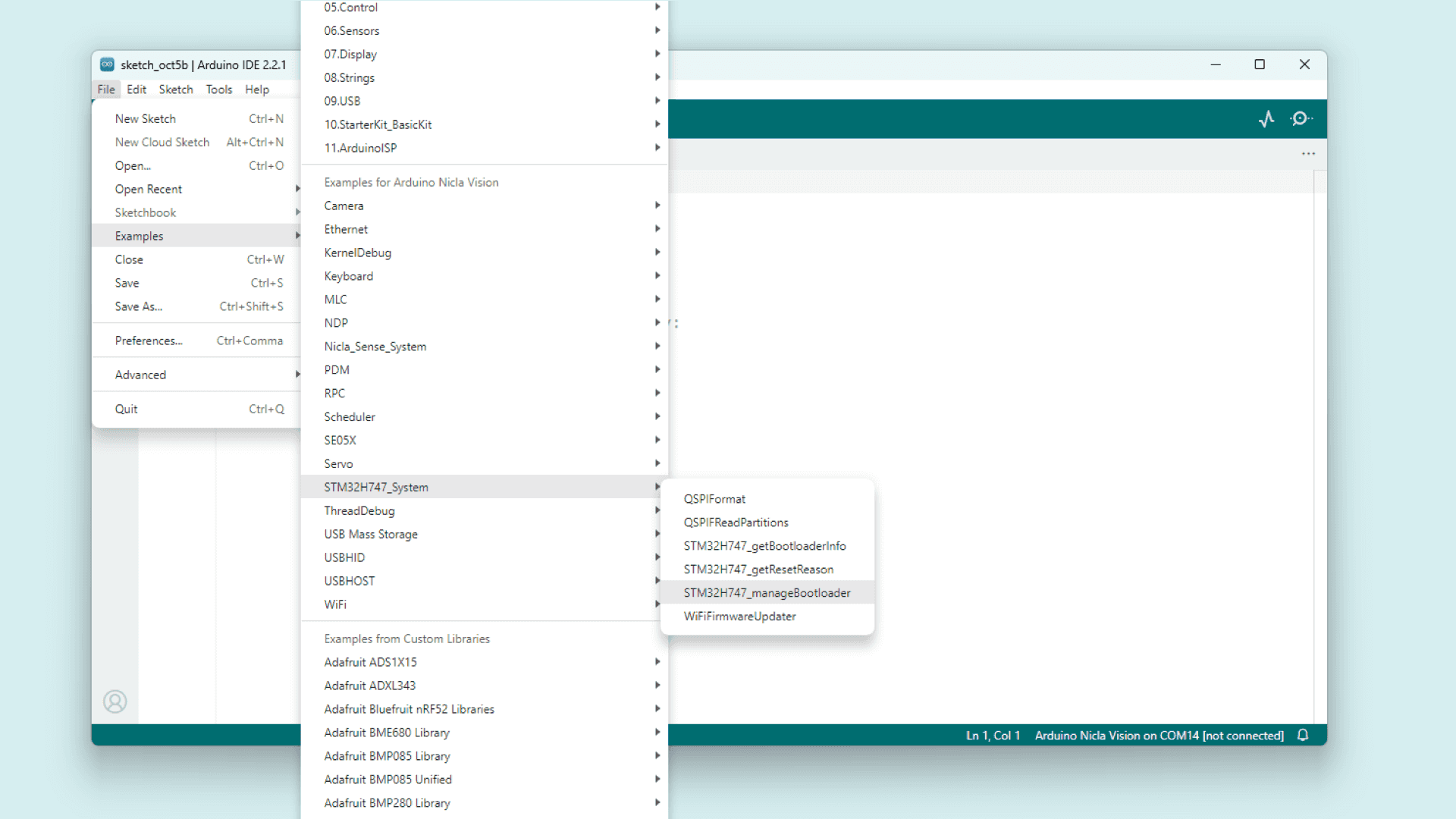
- Once the sketch is uploaded, proceed to follow the instructions provided in the Serial Monitor.
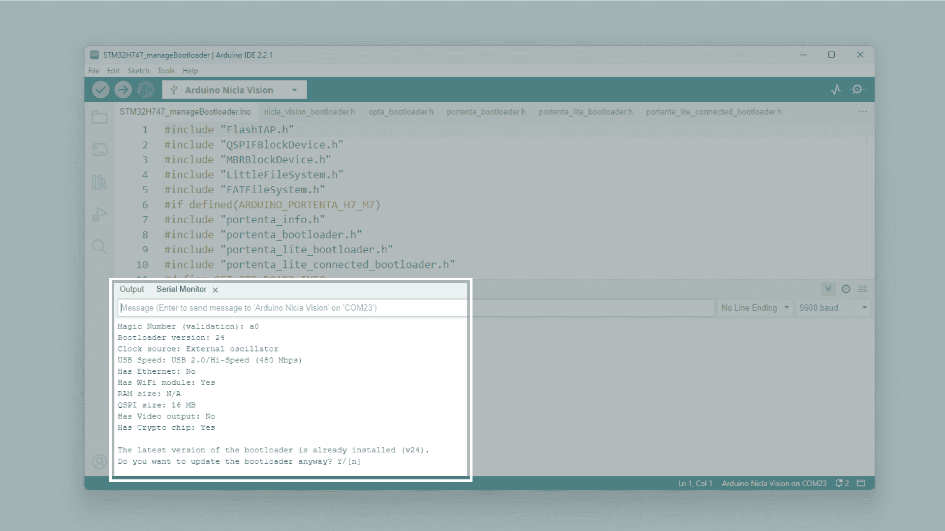
- If your Nicla Vision does not have the latest bootloader, simply type
"Y"in the input text box of the Serial Monitor, press Enter, and wait for the update to complete.
Tip: If you get the “error exit status 74”, verify you close each serial monitor window and you selected the board serial port correctly before trying again.
Step 2: Downloading the OpenMV IDE
Before beginning to program OpenMV scripts for the Nicla Vision, you must first download and install the OpenMV IDE.
Simply visit the OpenMV download page in your browser, select the latest version compatible with your operating system, and then follow the installation instructions provided by the installer.
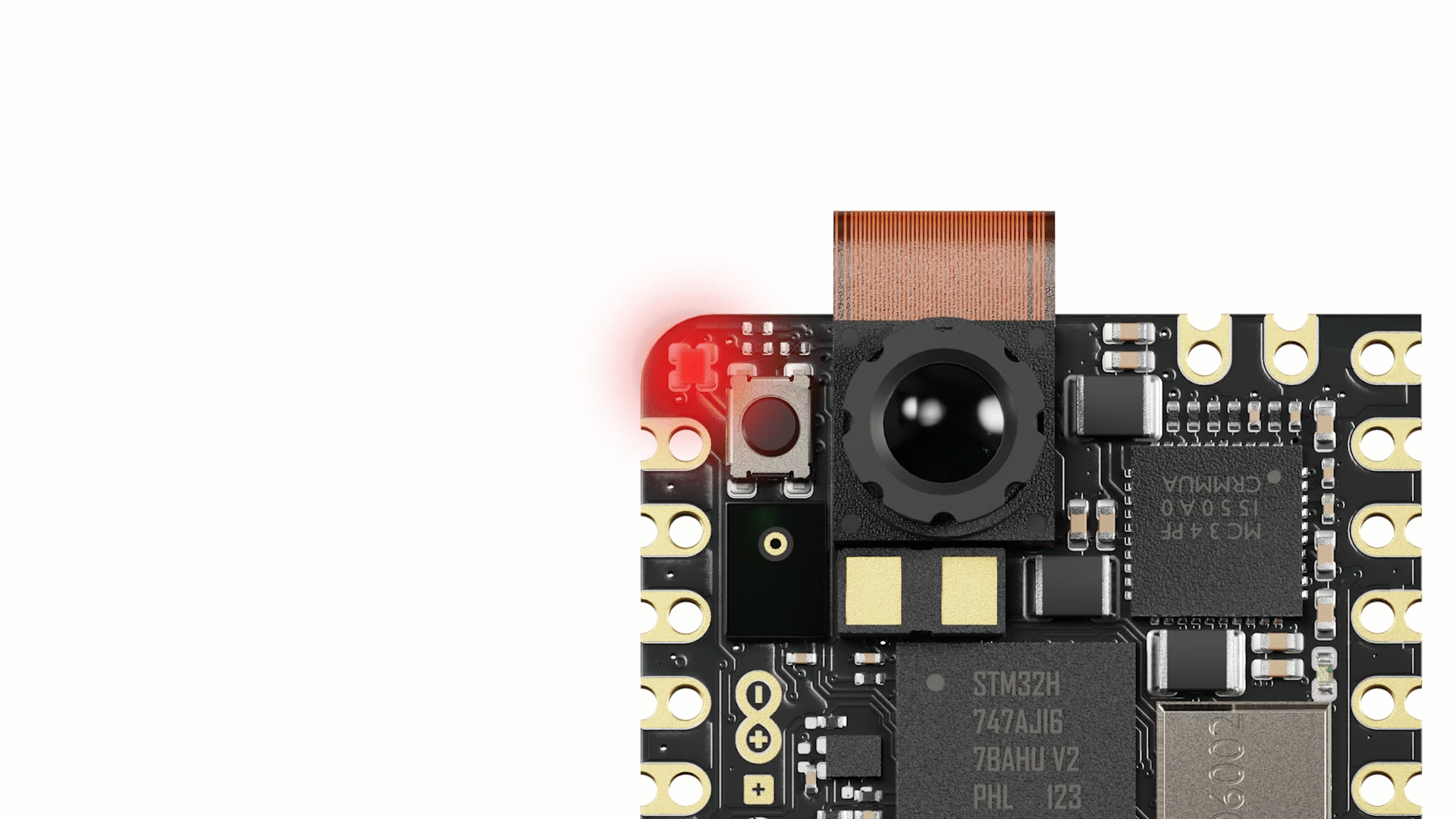
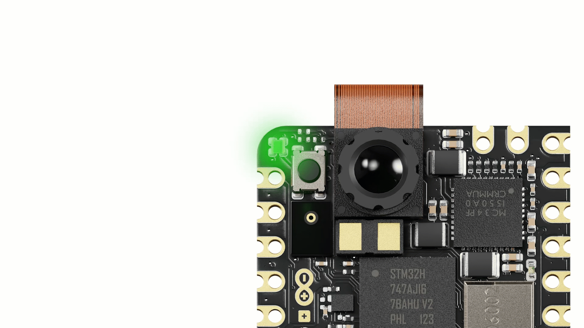
Step 3: Nicla Vision LED Codes
When utilising the Nicla Vision with OpenMV, the RGB LED on the board serves as an indicator of its current status, providing essential information:
🟢 Blinking Green: Indicates that the onboard bootloader of your Nicla Vision is active. This bootloader initiates for a brief period when the device is powered via USB, enabling the OpenMV IDE to reprogram the Nicla Vision.
🔵 Blinking Blue: Signals that your Nicla Vision is executing the default main.py script stored onboard.
In case you replace the main.py script with your own code, the Nicla Vision will execute your custom program instead.
Tip: If the blue LED is blinking but the OpenMV IDE fails to connect to your Nicla Vision, ensure that you are using a USB cable that provides both data and power when connecting your Nicla Vision to your PC.
⚪ Blinking White: Indicates a hardware failure causing a panic in the Nicla Vision firmware. Ensure that the camera module is securely installed if you encounter this status.
Tip: Pressing the Nicla Vision reset button once triggers a board reset, while pressing it twice activates Device Firmware Upgrade (DFU) mode, indicated by the green LED blinking and fading.
Step 4: Connecting to the OpenMV IDE
- Launch the OpenMV IDE and ensure the Nicla Vision is connected to your computer via the USB cable if not already done.
- Locate and click on the “connect” symbol located at the bottom of the left toolbar within the IDE.
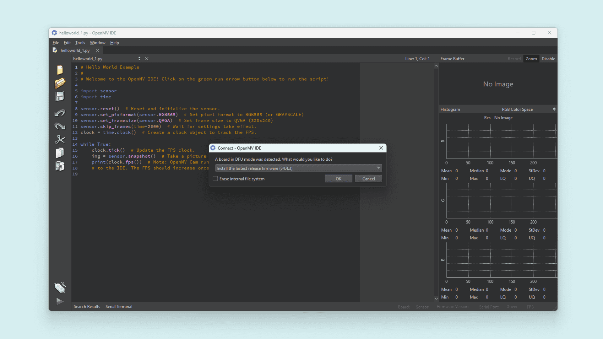
- If your Nicla Vision’s firmware is not up to date, a prompt will appear, requesting you to update it. The board will enter DFU mode, indicated by the fading green LED.
- Choose
Install the latest release firmwarefrom the prompt. This action will install the most recent OpenMV firmware on the Nicla Vision. You can opt to leave the option of erasing the internal file system unchecked. ClickOKto proceed.
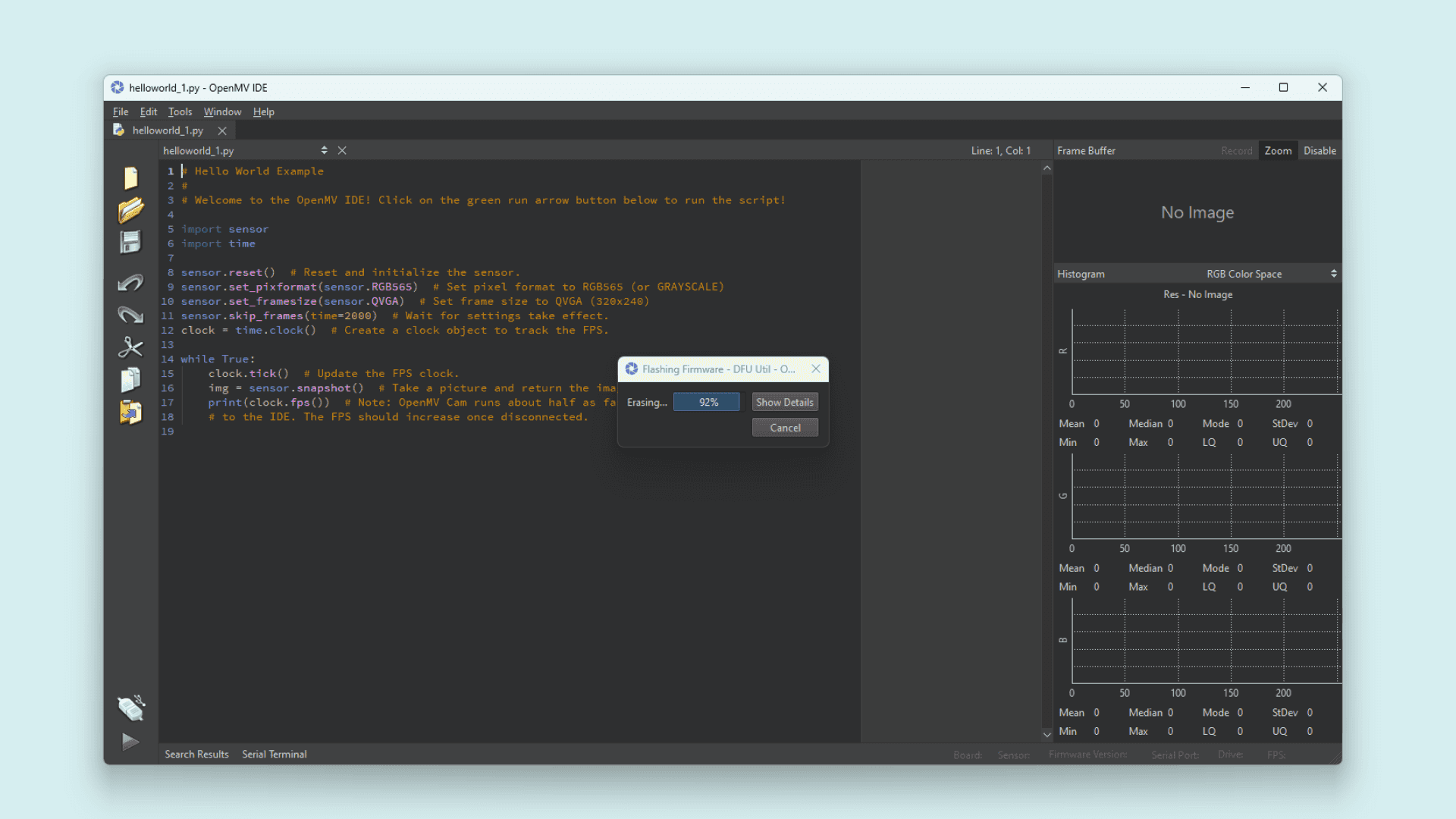
- The Nicla Vision’s green LED will begin flashing as the OpenMV firmware is uploaded. A loading bar will display the progress of the flashing.
- Wait until the green LED stops flashing and fading. Once complete, a message confirming
DFU firmware update complete!will appear.
- The board will signal readiness by flashing its blue LED. Confirm the completion dialog, and the Nicla Vision should now be connected to the OpenMV IDE. If not, click the “connect” button once more (the blue blinking should cease).
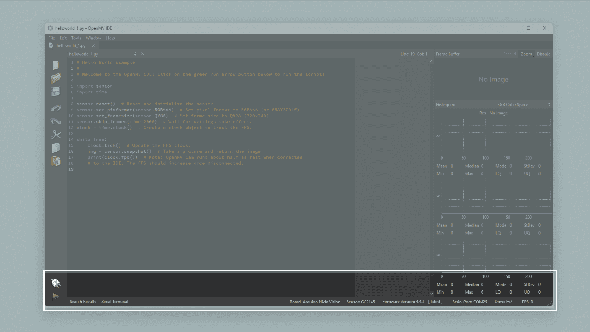
Step 5: Preparing the Script
Begin by creating a new script in the OpenMV IDE by selecting the “New File” button located in the toolbar on the left side. Import the necessary module, pyb:
import pyb # Import module for board related functionsIn Python®, a module is a distinct package of functionality. Importing it into your script makes its functionality accessible. For this illustration, only the pyb module is required, containing board-related functions like PIN handling. More information about its functions can be found here.
redLED = pyb.LED(1) # built-in red LED
greenLED = pyb.LED(2) # built-in green LED
blueLED = pyb.LED(3) # built-in blue LED
Next, you can define variables that will govern the behaviour of the built-in RGB LED. Utilising pyb, you can easily manage each colour independently. This enables you to distinctly identify and manipulate individual colours within the script.
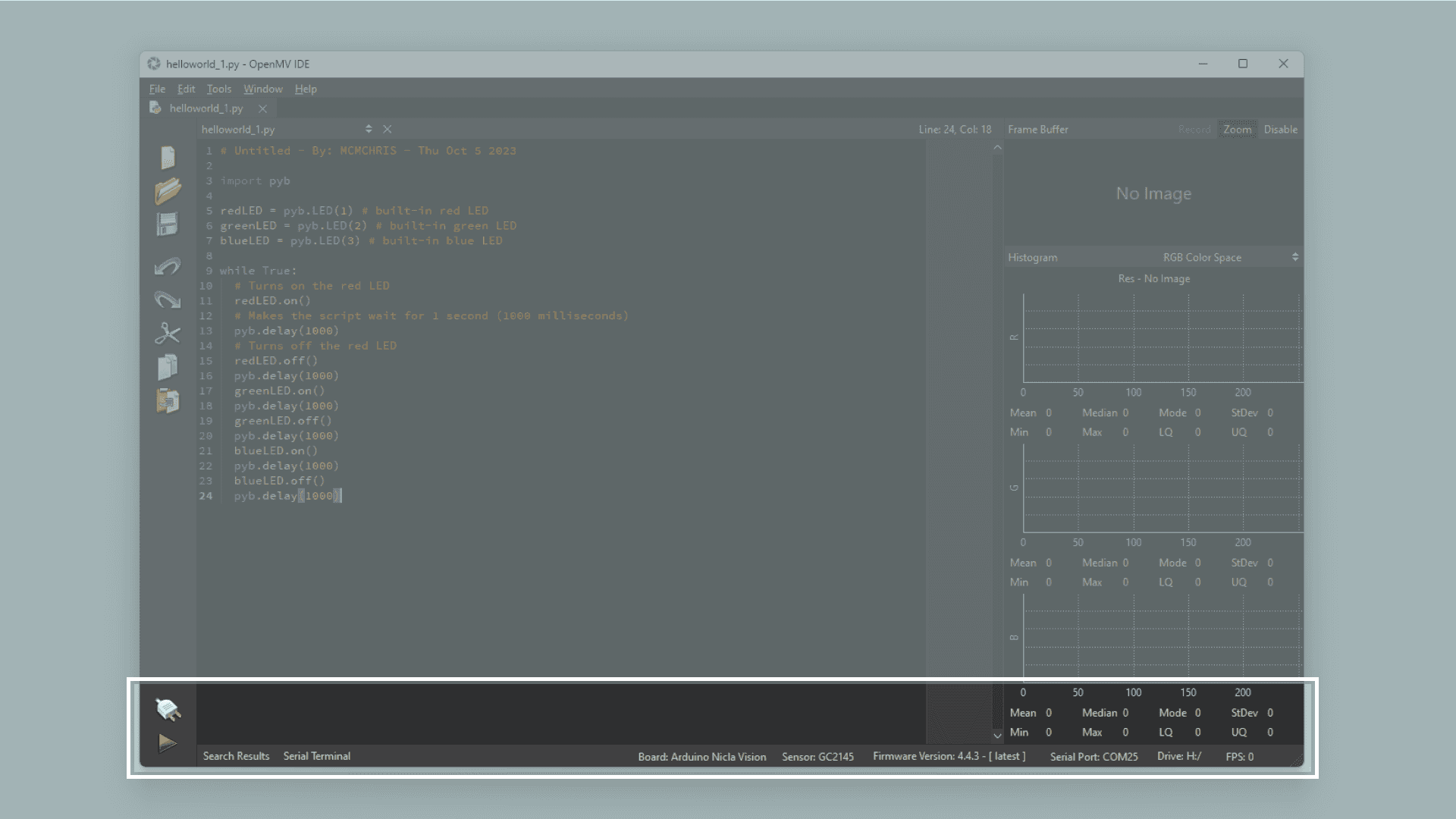
Step 6: Creating the Main Loop in the Script
Incorporating the code within a while loop ensures continuous execution. Within this loop, you can activate the LED using the on function, followed by implementing the delay function to introduce a pause. This delay initiates the execution of the subsequent instruction within the script. By adjusting the value within the parentheses, you can control the duration of the delay, with the number representing the milliseconds the board will wait. Upon completion of the specified time interval, you can deactivate the LED using the off function. This sequence can be repeated for each colour as needed.
while True:
  # Turns on the red LED
  redLED.on()
  # Makes the script wait for 1 second (1000 milliseconds)
  pyb.delay(1000)
  # Turns off the red LED
  redLED.off()
  pyb.delay(1000)
  greenLED.on()
  pyb.delay(1000)
  greenLED.off()
  pyb.delay(1000)
  blueLED.on()
  pyb.delay(1000)
  blueLED.off()
  pyb.delay(1000)
Step 7: Uploading the Script
Here you can see the complete blink script:
import pyb # Import module for board related functions

redLED = pyb.LED(1) # built-in red LED
greenLED = pyb.LED(2) # built-in green LED
blueLED = pyb.LED(3) # built-in blue LED

while True:

  # Turns on the red LED
  redLED.on()
  # Makes the script wait for 1 second (1000 milliseconds)
  pyb.delay(1000)
  # Turns off the red LED
  redLED.off()
  pyb.delay(1000)
  greenLED.on()
  pyb.delay(1000)
  greenLED.off()
  pyb.delay(1000)
  blueLED.on()
  pyb.delay(1000)
  blueLED.off()
  pyb.delay(1000)
Attach your board to the OpenMV IDE and upload the script above by clicking the play button located in the lower left corner.
Subsequently, the integrated LED on your Nicla Vision board should blink in the sequence of red, green, and blue repeatedly.
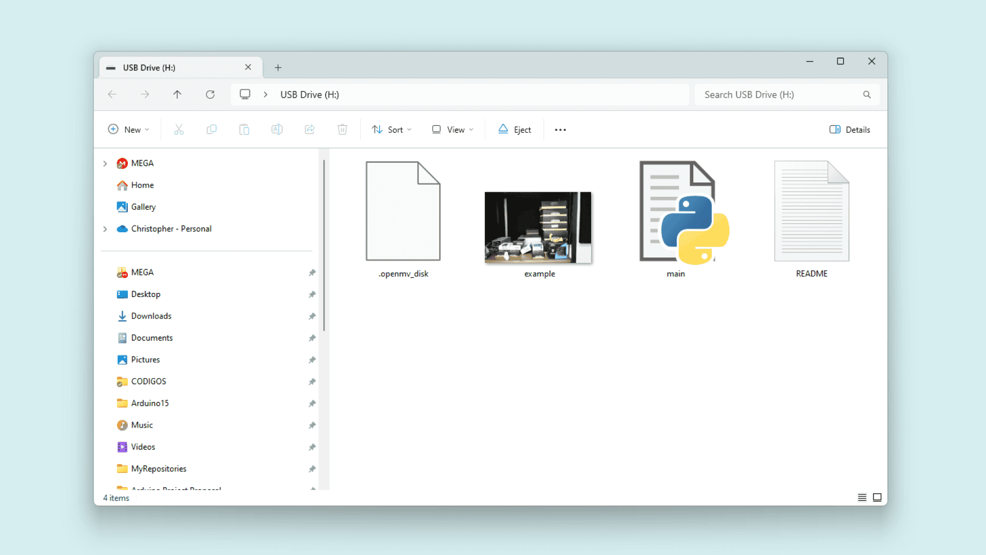
Step 8: Using the Nicla Vision Camera
You can effortlessly utilise the Nicla Vision camera via the OpenMV IDE. Below, you’ll find a concise script to configure the camera and capture a photo. The board will signal when it’s about to take a picture by blinking its LED.
Once taken, the photo will be stored in the Nicla Vision drive directory, accessible after resetting the board.
import pyb # Import module for board related functions
import sensor # Import the module for sensor related functions
import image # Import module containing machine vision algorithms

redLED = pyb.LED(1) # built-in red LED
blueLED = pyb.LED(3) # built-in blue LED

sensor.reset() # Initialize the camera sensor.
sensor.set_pixformat(sensor.RGB565) # Sets the sensor to RGB
sensor.set_framesize(sensor.QVGA) # Sets the resolution to 320x240 px
sensor.set_vflip(True) # Flips the image vertically
sensor.set_hmirror(True) # Mirrors the image horizontally

redLED.on()
sensor.skip_frames(time = 2000) # Skip some frames to let the image stabilize

redLED.off()
blueLED.on()

print("You're on camera!")
sensor.snapshot().save("example.jpg")

blueLED.off()
print("Done! Reset the camera to see the saved image.")
The Nicla Vision camera supports RGB 565 images, necessitating the use of sensor.set_pixformat(sensor.RGB565) to enable color image capture. Additionally, the camera resolution must be set, typically to sensor.set_framesize(sensor.QVGA).
Adjusting the image orientation can be achieved with sensor.set_vflip and sensor.set_hmirror functions. For instance, to ensure the correct perspective, use sensor.set_vflip(True) if the USB cable is facing downward.
Executing this script in OpenMV will display the captured image in the top right corner of the frame buffer. Initially, the onboard red LED will illuminate for a brief period, followed by the blue LED indicating the imminent photo capture. A message confirming the image capture will be printed in the serial terminal.
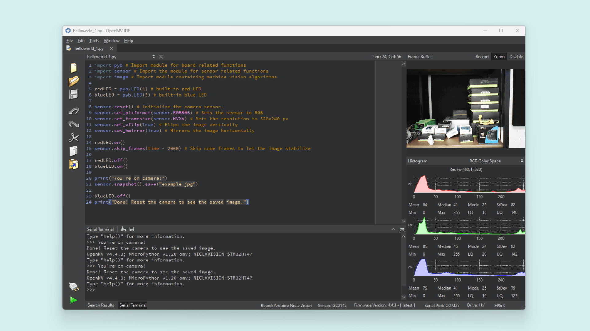
The captured image will be saved as "example.jpg" in the boards directory. It’s also feasible to save the image in ".bmp" format. Upon resetting the camera using the reset button, the image file will be visible in the boards directory.
Tip: If you’re attempting to use the built-in OpenMV IDE examples on macOS, you might encounter format compatibility issues. In such cases, consider using this converter tool if necessary.
Step 9: Using the Nicla Vision with Arduino IDE (Optional)
As mentioned earlier, the Nicla Vision comes with pre-installed OpenMV firmware, simplifying its usage with OpenMV straight out of the box. However, it’s also possible to utilise the Nicla Vision with the Arduino IDE.
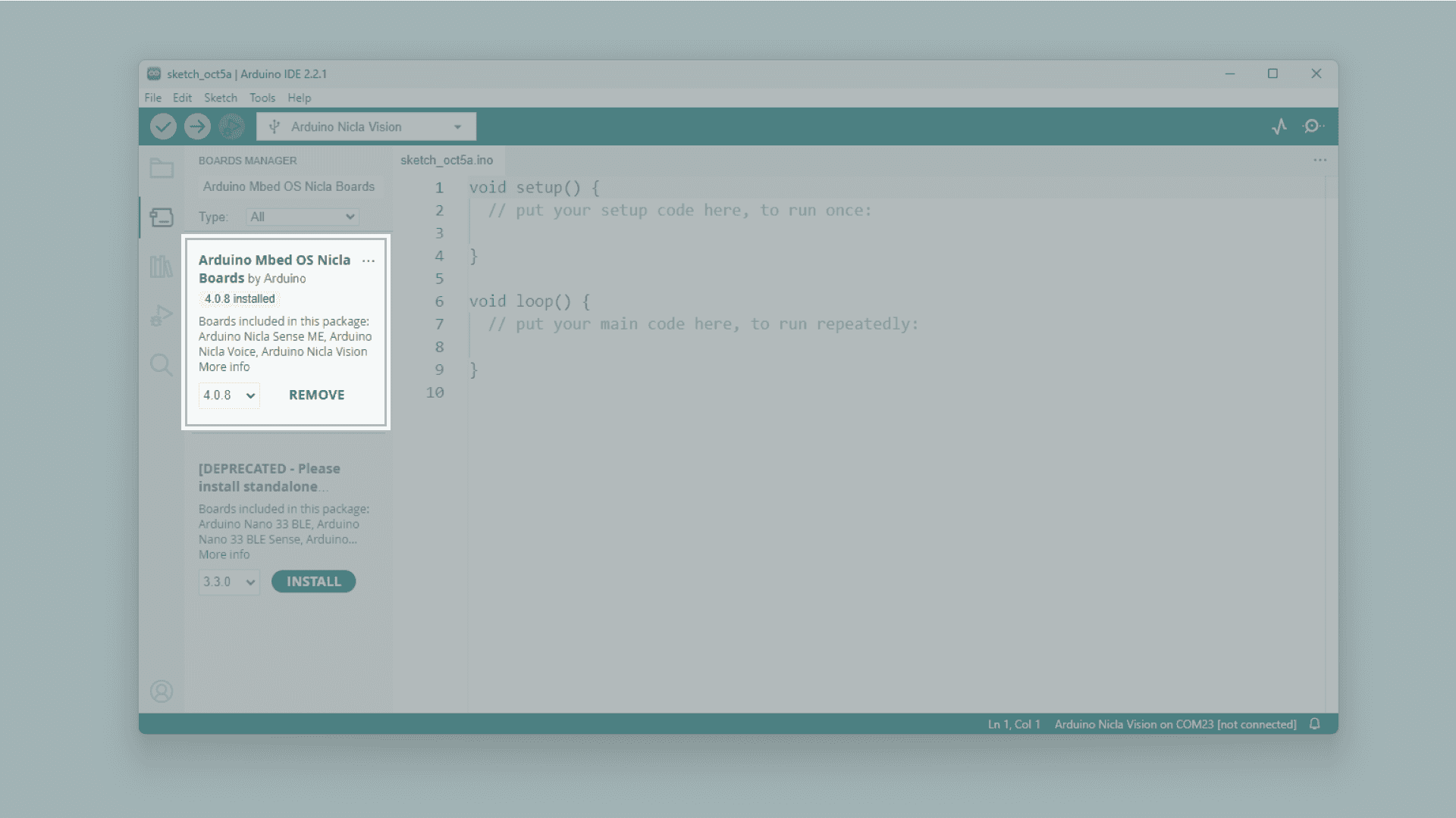
Begin by ensuring that you have the latest core installed. Navigate to Tools > Board > Boards Manager… and search for Mbed OS Nicla Boards in the Boards Manager window, then proceed to install it.
Once the core is installed and your board is connected to your computer, select the port to which the board is connected and the board core.
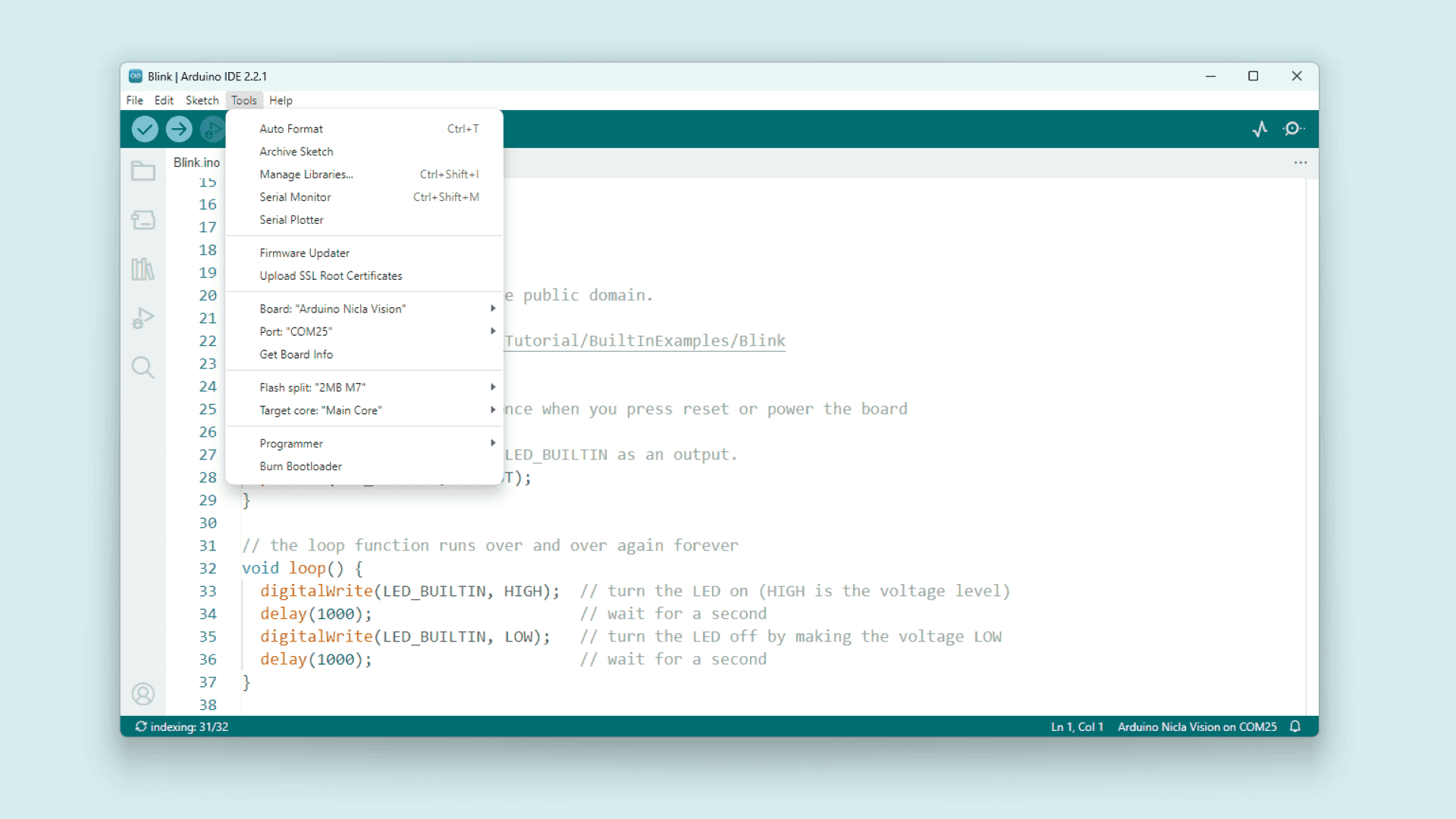
Navigate to File > Examples > 01.Basics > Blink to access the Blink example. From there, you can upload an Arduino sketch to the board by clicking the “Upload” button.
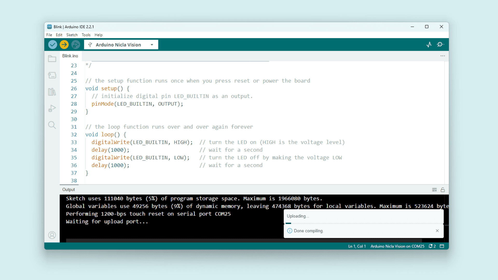
The board should commence blinking its onboard green LED upon successful upload.
If you intend to revert to using the board with OpenMV after utilising it with the Arduino IDE, you’ll need to enter bootloader mode and install the OpenMV firmware. This can be accomplished by double-pressing the reset button next to the LED. Once the board is in bootloader mode and connected to your computer, follow the steps outlined in the “Connecting to the OpenMV IDE” section above to reconnect the board to the OpenMV IDE.
Summary
In this tutorial, you’ve gained proficiency in utilising the OpenMV IDE with your Arduino Nicla Vision board. You’ve also acquired the skills to manage the Nicla Vision’s RGB LED using MicroPython functions and to deploy scripts to your board through the OpenMV IDE.
Next Steps:
- Explore the capabilities of MicroPython further. For inspiration, explore the examples provided within the OpenMV IDE by navigating to File > Examples > Arduino.
- Consider leveraging the board for more advanced image processing tasks. Explore additional tutorials to expand your knowledge.
This getting started guide was originally published on arduino.cc
Troubleshooting
If you’re encountering Issues with OpenMV Firmware Flashing:
- If the firmware upload fails during the process, re-enter bootloader mode on the board and attempt the upload again. Repeat this process until the firmware uploads successfully.
- If the OpenMV IDE still fails to connect after flashing the firmware, consider uploading the latest firmware manually using the “Load Specific Firmware File” option. Locate the latest firmware in the OpenMV Github repository, typically named firmware.bin.
- In case you encounter an “OSError: Reset Failed” message, perform a board reset by pressing the reset button. Wait until the blue LED begins flashing, then reconnect the board to the OpenMV IDE and retry running the script.

Arduino® PRO isn’t just about technology; it’s about empowering professional developers to dive into the future with ease. With added flexibility and reduced lock-in risks, it paves the way for quicker tech adoption by equipping engineers with the tools to eliminate repetitive tasks and coding, freeing them up to focus on the end application.
It’s all about simplicity, scalability, and security and can offer ground-breaking innovations in the Aviation, Industry 4.0, Health and Safety, Smart Buildings and Connected World, Robotics, Automotive, and Smart Agriculture.
Discover exactly what Arduino is capable of:

Let’s invent the future together
What’s your challenge? From augmented reality to machine learning and automation, send us your questions, problems or ideas… we have the solution to help you design the world. Get in touch today.

Visit our Blogs, Getting Started Guides and Projects for more inspiration!