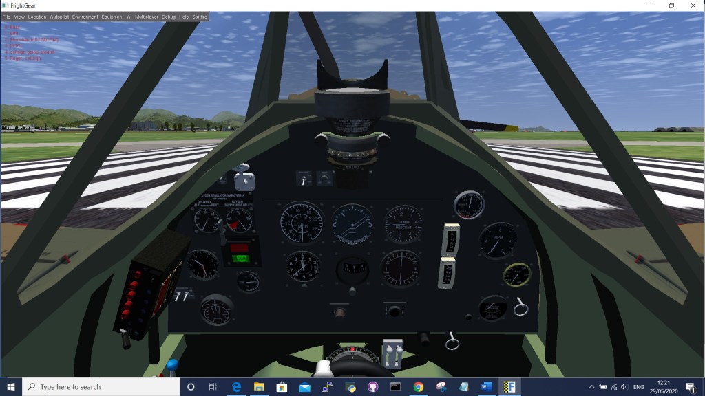
Remembering complicated keyboard commands whilst playing a game is a real pain, especially when there are lots of controls like in FlightGear’s Spitfire simulator. That’s why we built a custom control panel with real switches and buttons to make the in-flight experience much more realistic.
Although this control panel was built specifically for this Spitfire simulator, with a bit of ingenuity, it is possible to make controllers for any game or simulator that uses keyboard input using an Arduino and a simple circuit. Only the Micro, Leonardo and Nano 33 IoT boards are capable of emulating a USB keyboard, so you must use one of these.
The Spitfire aircraft chosen for this project has an authentic start-up procedure that closely follows the original Pilot’s Operational Handbook, a copy of which is included with the download. Now, using the controller to load the Coffman starter cartridge, switch on the magneto’s, priming the carburettors and firing up the V-12 Rolls-Royce Merlin engine is a much more authentic experience. Leaving us to concentrate on flying gracefully through the air!
1. Install the software
FlightGear is a sophisticated open-source flight simulator for use in research environments, pilot training and for fun. It is available as a free download on Mac / Windows & Linux systems from https://www.flightgear.org/. Once downloaded follow the installation instructions.
2. Build the circuit
Control
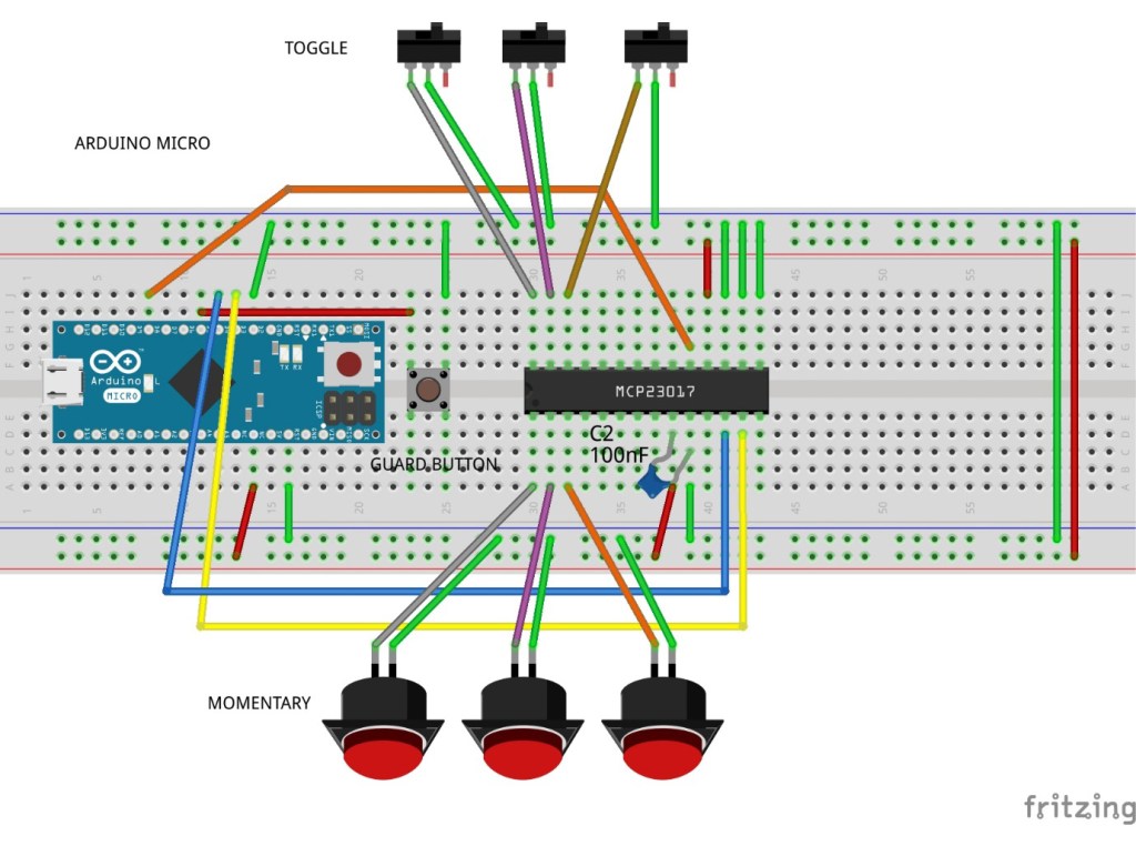
At the heart of the circuit used to detect the buttons and switches is a Microchip MCP23017 I/O port expander IC. It uses the I2C interface on the Arduino and each chip is capable of controlling 16 inputs/outputs. They can also be chained together so you can connect a large number of buttons and switches using just 2 pins on the Arduino. This leaves plenty of room for adding further controls.
The circuit was tested on a breadboard before a permanent version was made using prototyping board with soldered components.
Buttons & Switches
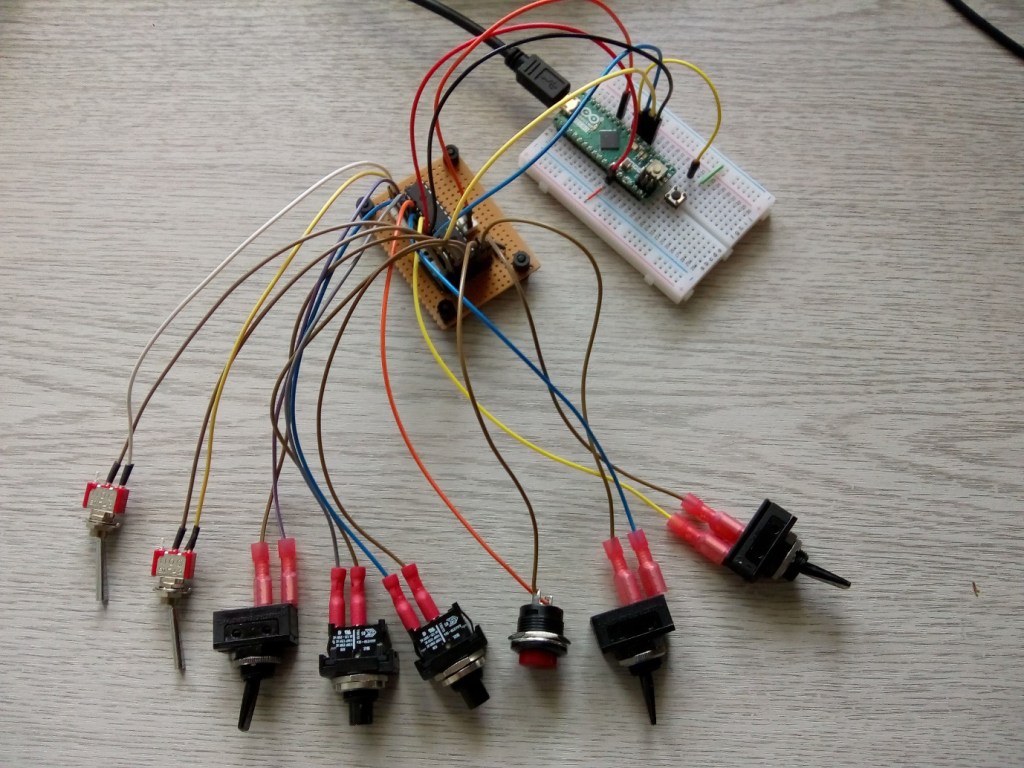
We used 3 different types of switches and buttons to add interest and authenticity to the control panel and to show how they can interact with the simulator.
For controls that are either on/off, or up/down, like the magnetos, flaps and undercarriage gear, SPST or SPDT latching toggle switches work well. They can send the same key code for both on and off states, for when a control toggles, in the case of the magnetos or a separate code for each state used by the flaps.
Some controls like the engine starter button needed to be pressed and held down. This requires a momentary button that can be held in the on state and released for off, just like a keyboard key. These can be made to issue multiple key codes in a stream using the keyboard library.
We also used latching Push Buttons for the Coffman Cartridge loader and Fuel Primer Plunger as they had a nice click action. For these to work the software had to emulate a Momentary Button.
We experimented with different button / Arduino keyboard commands to send the correct key codes to FlightGear. We could not get the ‘{‘ and ‘}’ keycodes used to toggle the magnetos to work, so we reassigned them to keys that do not require shift on the keyboard, like U and u using the FlightGear configuration file. http://wiki.flightgear.org/Howto:Reassign_keyboard_bindings
Connections
| Arduino Micro pin | MCP23017 | Button |
|
5V |
5V |
|
| GND | GND | |
| SDA | SDA | |
| SCL | SCL | |
| D7 | INTB | |
| D2 | Guard button | |
| GPB0 | L Magneto | |
| GPB1 | R Magneto | |
| GPB2 | Gear up/down | |
| GPB3 | Flaps up/down | |
| GPB4 | Canopy open/close | |
| GPB5 | Coffman cartridge | |
| GPB6 | Fuel priming pump | |
| GPB7 | Engine start |
Each control button or switch is connected to its own MCP23017 port and GND. No current limiting resistors are needed as the internal pull-ups in the chip were configured in the firmware.
One difficulty of using the Arduino to emulate a keyboard is, that if there is a coding error, the device can keep sending keystrokes to the IDE, which hinders re-programming. To avoid this, a guard push button (set as INPUT-PULLUP) on pin D2 was used which waits to be pressed before the keyboard.begin() function is called. If a code error occurs, pressing reset on the Arduino allows it to be re-flashed. The program will not run until the guard button is pressed. Once everything is tested the button can be permanently set to LOW (on) by connecting pin D2 to ground.
3. Programme the Arduino
You’ll need the Arduino IDE before anything else, you can find out how to do it here.
The Arduino code uses the Keyboard library which comes built-in with the IDE. This generates keyboard codes and sends them over the USB connection. To the simulator, they look just like someone has pressed a key on the keyboard.
There are numerous code examples available to drive the MCP23017. We based ours on the example from Nick Gammon http://www.gammon.com.au/forum/?id=10945
To work well with the simulator, buttons and switches must be highly responsive and it is important not to miss a keypress. This is achieved by using the interrupt capability of the MCP23017 and Arduino.
The setup code deals with initialising the MCP23017 registers according to the datasheet, initialising the keyboard functions and setting up the interrupt routine. This fires the interrupt handler each time a button or switch state change is detected.
The keyboard characters sent by each control are defined at the top of the listing. The keyboard handler contains a switch statement which links each control to its keypress. An action is associated with both the on and off states of the control and there is also a test to see if the state has changed. If more controls are added, just add further definitions and case clauses.
The interrupt handler fires whenever a button or switch is operated. Latched switches fire it once only when they change state. Momentary buttons fire the handler twice, once when they are pressed and once when they are released. It is important to time this so both state changes are intercepted which is why there is a slight delay between the press and release functions.
The assumption is made that when the simulator starts, any switches are in the correct starting position so that they will be synchronised with the simulator.
Test the code using serial print statements sent to the Arduino serial console to get all the logic working before adding in the keyboard command functions. The LED attached to pin 13 also flashes when a control is activated. Once everything is debugged, the print statements can be commented out or removed.
// Author: Peter Milne
// Date: May 2020

// FlightGear Spitfire IIa controller using MCP23017
// MCP23017 driver adapted from code by Nick Gammon

#include <Wire.h>
#include <Keyboard.h>

// Spitfire controls
const char LEFT_MAGNETO = 'U';  // GPB0
const char RIGHT_MAGNETO = 'u'; // GPB1
const char FLAPS_UP = '[';  // GPB2
const char FLAPS_DOWN = ']';  //GPB2
const char COFFMAN_CARTRIDGE = 'C';  // GPB3
const char PRIMING_PUMP = 'I';  // GPB4
const char COFFMAN_STARTER = 's';  // GPB5
const char CANOPY_CLOSE = 'f';  // GPB6
const char CANOPY_OPEN = 'F';  // GPB6
const char GEAR_UP = 'g';  // GPB7
const char GEAR_DOWN = 'G';  // GPB7

const int start_button = 4;
const int int_pin = 7;

int previousButtonState[16];

// MCP23017 registers (everything except direction defaults to 0)
#define IODIRA   0x00   // IO direction  (0 = output, 1 = input (Default))
#define IODIRB   0x01
#define IOPOLA   0x02   // IO polarity   (0 = normal, 1 = inverse)
#define IOPOLB   0x03
#define GPINTENA 0x04   // Interrupt on change (0 = disable, 1 = enable)
#define GPINTENB 0x05
#define DEFVALA  0x06   // Default comparison for interrupt on change (interrupts on opposite)
#define DEFVALB  0x07
#define INTCONA  0x08   // Interrupt control (0 = interrupt on change from previous, 1 = interrupt on change from DEFVAL)
#define INTCONB  0x09
#define IOCON    0x0A   // IO Configuration: bank/mirror/seqop/disslw/haen/odr/intpol/notimp
//#define IOCON 0x0B  // same as 0x0A
#define GPPUA    0x0C   // Pull-up resistor (0 = disabled, 1 = enabled)
#define GPPUB    0x0D
#define INFTFA   0x0E   // Interrupt flag (read only) : (0 = no interrupt, 1 = pin caused interrupt)
#define INFTFB   0x0F
#define INTCAPA  0x10   // Interrupt capture (read only) : value of GPIO at time of last interrupt
#define INTCAPB  0x11
#define GPIOA    0x12   // Port value. Write to change, read to obtain value
#define GPIOB    0x13
#define OLLATA   0x14   // Output latch. Write to latch output.
#define OLLATB   0x15
#define port 0x20  // MCP23017 is on I2C port 0x20

#define ISR_INDICATOR 12  // pin 12
#define ONBOARD_LED 13    // pin 13

volatile bool keyPressed;

// set register "reg" on expander to "data"
// for example, IO direction
void expanderWriteBoth (const byte reg, const byte data ){
  Wire.beginTransmission (port);
  Wire.write (reg);
  Wire.write (data);  // port A
  Wire.write (data);  // port B
  Wire.endTransmission ();
} // end of expanderWrite

// read a byte from the expander
unsigned int expanderRead (const byte reg){
  Wire.beginTransmission (port);
  Wire.write (reg);
  Wire.endTransmission ();
  Wire.requestFrom (port, 1);
  return Wire.read();
} // end of expanderRead

// interrupt service routine, called when pin D2 goes from 1 to 0
void keypress () {
  digitalWrite (ISR_INDICATOR, HIGH);  // debugging
  keyPressed = true;   // set flag so main loop knows
}  // end of keypress

void setup (){
  pinMode (ISR_INDICATOR, OUTPUT);  // for testing (ISR indicator)
  pinMode (ONBOARD_LED, OUTPUT);  // for onboard LED
  pinMode(start_button, INPUT_PULLUP);

  Wire.begin ();
  Serial.begin (115200);

  // Safe start for testing - only start after button press
  while (digitalRead(start_button));

  Keyboard.begin();
  delay(5000);
  Serial.println ("Starting ...");

  expanderWriteBoth (IOCON, 0b01100000); // mirror interrupts, disable sequential mode
  expanderWriteBoth (GPPUA, 0xFF);   // pull-up resistor for switch - both ports
  expanderWriteBoth (IOPOLA, 0xFF);  // invert polarity of signal - both ports
  expanderWriteBoth (GPINTENA, 0xFF); // enable interrupts - both ports

  keyPressed = false;  // no interrupt yet
  // read from interrupt capture ports to clear them
  expanderRead (INTCAPA);
  expanderRead (INTCAPB);

  // Must be interrupt capable pin
  attachInterrupt(digitalPinToInterrupt(int_pin), keypress, FALLING);
}  // end of setup

// time we turned LED on
unsigned long time = 0;
unsigned int keyValue = 0;
bool firstRun = true;

// called from main loop when we know we had an interrupt
void handleKeypress () {
  delay (50);  // de-bounce before we re-enable interrupts

  keyPressed = false;  // ready for next time through the interrupt service routine
  digitalWrite (ISR_INDICATOR, LOW);  // debugging

  // Read port values, as required. Note that this re-arms the interrupts.
  if (expanderRead (INFTFA)){
    keyValue &= 0x00FF;
    keyValue |= expanderRead (INTCAPA) << 8;    // read value at time of interrupt
  }
  if (expanderRead (INFTFB)){
    keyValue &= 0xFF00;
    keyValue |= expanderRead (INTCAPB);        // port B is in low-order byte
  }

  Serial.println ("Button states");
  Serial.println ("0                   1");
  Serial.println ("0 1 2 3 4 5 6 7 8 9 0 1 2 3 4 5");

  unsigned int buttonState = 0;
  // display which buttons were down at the time of the interrupt
  for (byte button = 0; button < 16; button++) {
    if (buttonState = (keyValue & (1 << button)) >> button) {
      Serial.print("1 ");
      if (buttonState != previousButtonState[button]) {
        switch (button) {
          case 0: Keyboard.write(LEFT_MAGNETO); break; // Latch
          case 1: Keyboard.write(RIGHT_MAGNETO); break;
          case 2: Keyboard.write(GEAR_UP); break;
          case 3: Keyboard.write(FLAPS_DOWN); break;
          case 4: Keyboard.write(CANOPY_CLOSE); break;
          case 5: if (!firstRun) {
              Keyboard.press(COFFMAN_CARTRIDGE);  // Latch as momentary
              delay(100);
              Keyboard.release(COFFMAN_CARTRIDGE);
            } break;
          case 6: if (!firstRun) {
              Keyboard.press(PRIMING_PUMP);
              delay(100);
              Keyboard.release(PRIMING_PUMP);
            } break;
          case 7: Keyboard.press(COFFMAN_STARTER); break;
          default: break;
        }
      }
    } else {
      Serial.print(". ");
      if (buttonState != previousButtonState[button]) {
        switch (button) {
          case 0: Keyboard.write(LEFT_MAGNETO); break;
          case 1: Keyboard.write(RIGHT_MAGNETO); break;
          case 2: Keyboard.write(GEAR_DOWN); break;
          case 3: Keyboard.write(FLAPS_UP); break;
          case 4: Keyboard.write(CANOPY_OPEN); break;
          case 5: if (!firstRun) {
              Keyboard.press(COFFMAN_CARTRIDGE);
              delay(100);
              Keyboard.release(COFFMAN_CARTRIDGE);
            } break;
          case 6: if (!firstRun) {
              Keyboard.press(PRIMING_PUMP);
              delay(100);
              Keyboard.release(PRIMING_PUMP);
            } break;
          case 7: Keyboard.release(COFFMAN_STARTER); break;
          default: break;
        }
      }
    }
    previousButtonState[button] = buttonState;  // Capture state for next time
  }
  firstRun = false;

  Serial.println ("Next");

  // if a switch is now pressed, turn LED on  (key down event)
  if (keyValue) {
    time = millis ();  // remember when
    digitalWrite (ONBOARD_LED, HIGH);  // on-board LED
  }  // end if
}  // end of handleKeypress

void loop () {
  // was there an interrupt?
  if (keyPressed)
    handleKeypress ();

  // Do other stuff in here
  // turn LED off after 500 ms
  if (millis () > (time + 500) && time != 0) {
    digitalWrite (ONBOARD_LED, LOW);
    time = 0;
  }  // end if time up
}  // end of loop
4. Building and testing
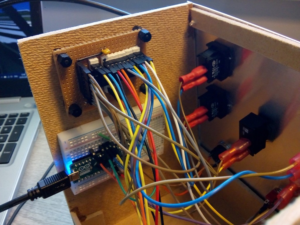
Once the breadboard circuit was sending the correct key codes with all the switches hooked up, the simulator was started to check everything was working. We then made a permanent circuit using prototype board and soldered connections. The switches were hooked up to PCB headers using Dupont wires with crimp connectors on one end. The Arduino was mounted on a breadboard so it could be fixed in the enclosure. Everything was now ready to be mounted on a panel.
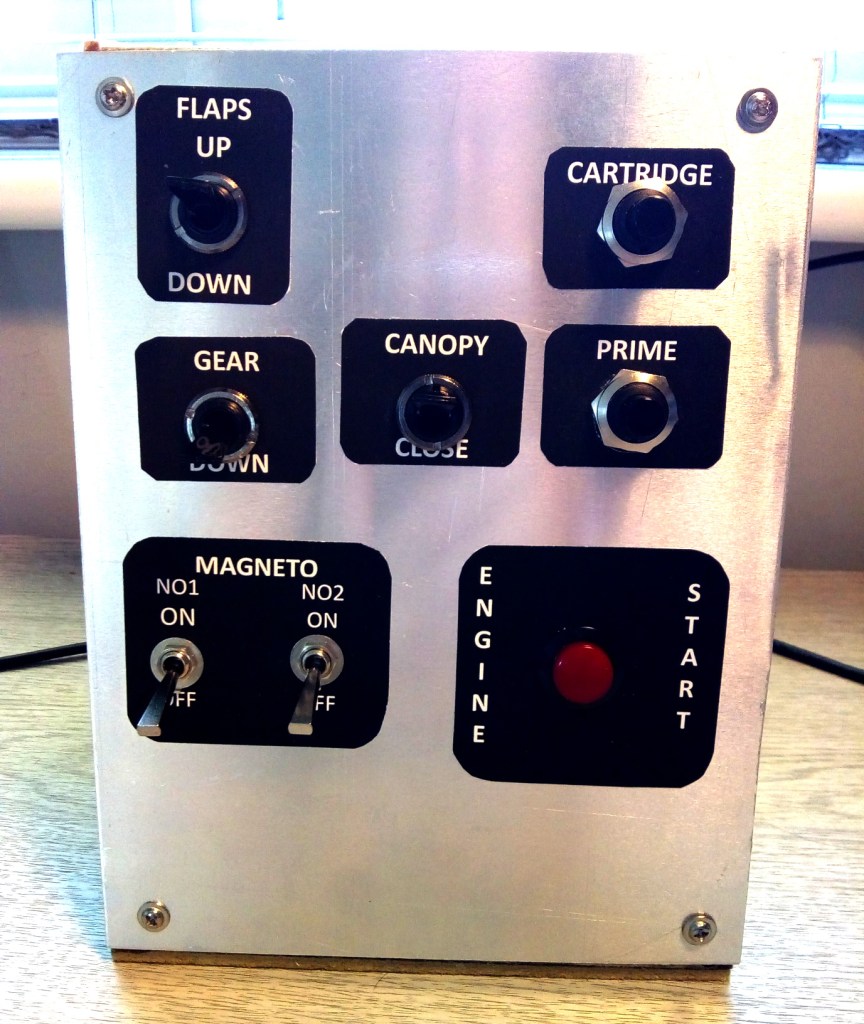
The panel was made from aluminium 1.5mm sheet (150mm x 200mm) using a template drawn in PowerPoint. This was printed on a laser printer and used to position the centre point of each switch. We used a centre punch to mark the hole position before drilling pilot holes and then enlarging them using a taper drill bit.
A box was made from fibreboard glued together with super-glue. The panel was mounted on the front of the box using 4 self-tapping screws.
Before fitting the switches, the laser printed labels were attached to the panel using double-sided tape. The switches are organised in a similar fashion to the actual Spitfire cockpit layout and we tried to give it a vintage look.
Summary
With a little ingenuity and an Arduino and fairly simple electronic circuit, it is possible to make a game controller that really enhances the gameplay or simulation.
For our FlightGear Spitfire controller, we focussed on building a panel that would enable us to enjoy the authentic experience of starting up this historic aircraft and preparing for take-off.
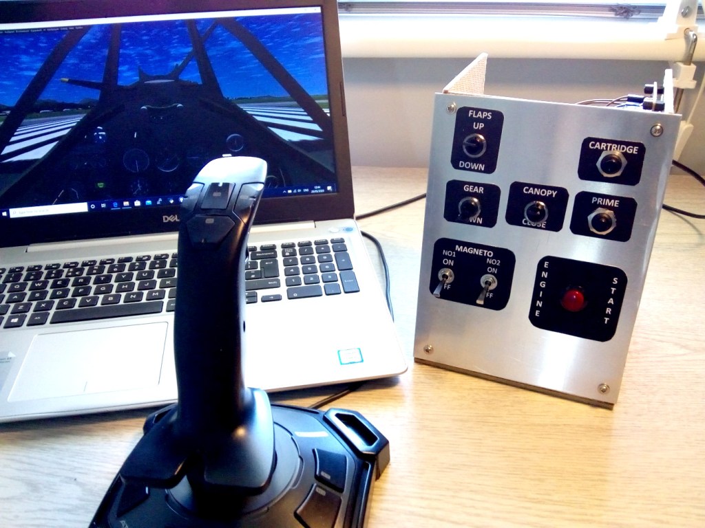
Used in conjunction with a Joystick, which controls the aircraft flying surfaces and brakes, we were able to enjoy the thrill of flying this classic Spitfire aircraft and intend to add rudder foot controls next!
The techniques used in the project can be applied to any game or simulator that uses keyboard input to issue commands, so we hope you will have fun building one for your favourite game.
Like what you read? Why not show your appreciation by giving some love.
From a quick tap to smashing that love button and show how much you enjoyed this project.

