This is a very simple project, ideal for kids as it uses Scratch, a visual programming environment which is great to start learning about programming. It will see you through some basics of using a Raspberry Pi, programming and circuit making.
You should start the project with an already set-up Raspberry Pi running the latest noobs. You can learn how to do that here.
1. Prepare LED connections

- Connect a jumper wire to the positive (longer) leg of the LED and to any leg of the 3.3K Ohm resistor
- Connect another jumper wire to the other leg of the 3.3K Ohm resistor
- Connect a jumper wire to the negative (shorter) leg of the LED
It doesn’t matter which colour jumper wires you use, but for clarity, it’s a good idea to use black for negative and red for positive polarities.
Ensure that the resistor is connected to the positive leg of the LED
2. Connect LED to Raspberry Pi
- Connect mouse, keyboard and monitor to the Raspberry Pi and power it up. You can learn how to do it here
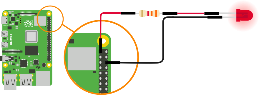
- Connect the jumper wire attached to the resistor to the 3V3 pin (top left) on the Raspberry Pi
- Connect the other jumper wire attached to the resistor to the GND pin (3rd right) on the Raspberry Pi
Your LED should now be on.
This was a quick test to ensure that everything works fine.
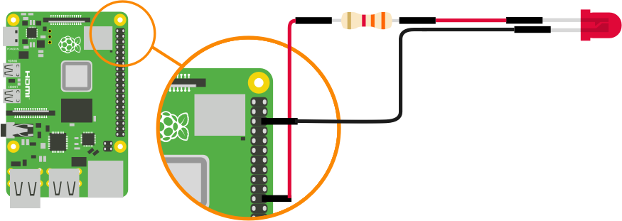
- Disconnect the jumper wire attached to the resistor from the 3V3 pin
- Connect the jumper wire attached to the resistor to pin GP25 (11 on the right column)
3. Open & prepare Scratch 2
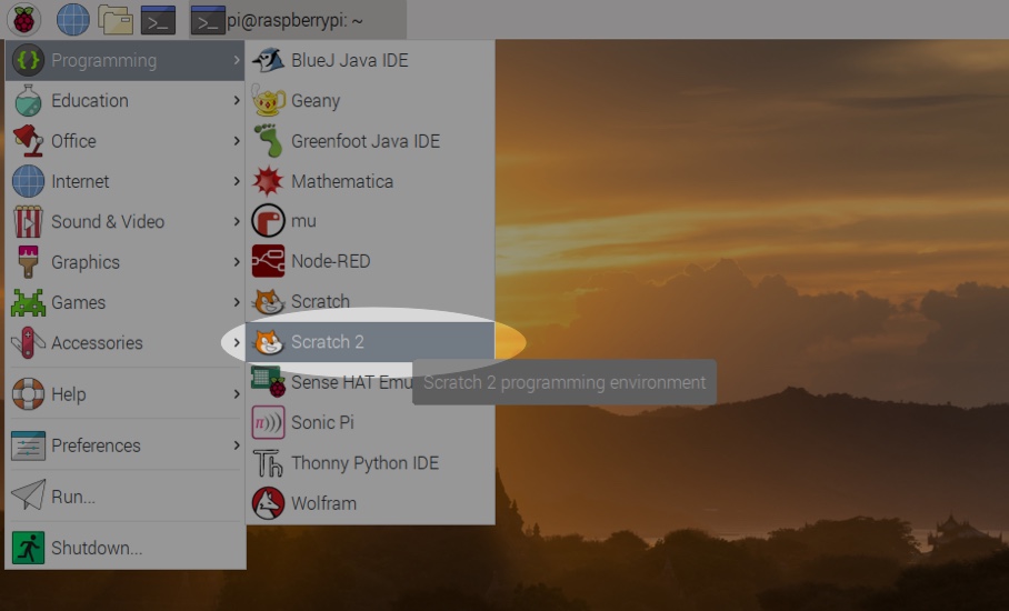
- Navigate to the Raspberry icon on the top left of your Raspberry Pi’s desktop and open “Scratch 2” from the “Programming“ menu
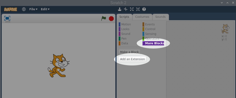
- Ignore the cat
- Click on “More Blocks”
- Click on “Add an Extension”
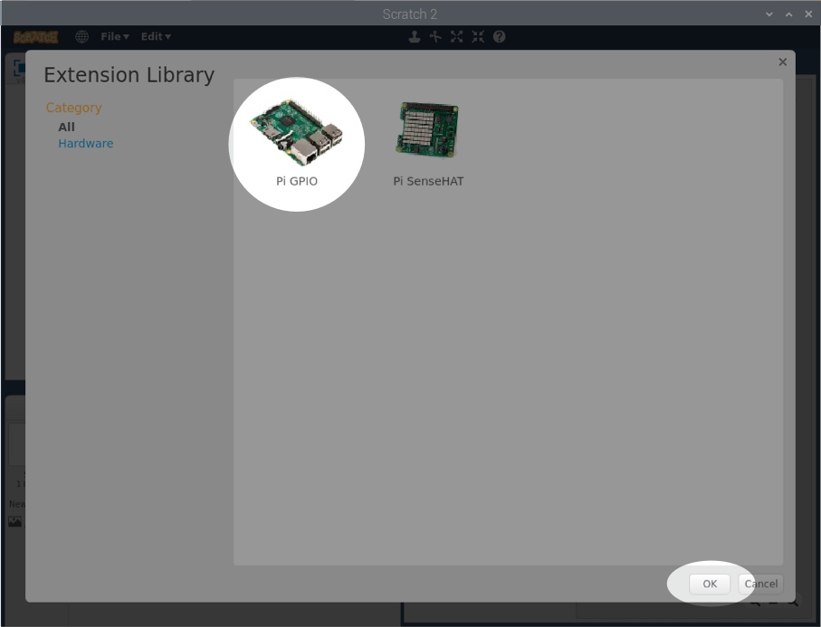
- Select “Pi GPIO” and click “Ok”
4. Programme LED
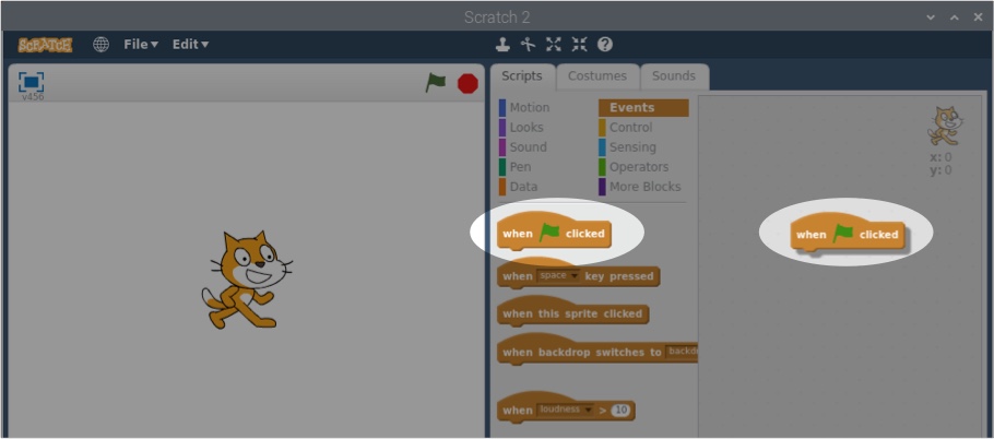
- From the “Events” menu in Scratch 2, drag “when clicked” into the right-hand panel

- Drag “repeat” from the “Control” menu and attach it to “when clicked”
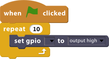
- Drag “set gpio” from the “More Blocks” menu into “repeat”. Select “25” from the “set gpio” dropdown
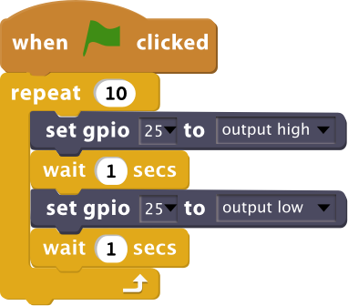
- Drag “wait secs” from the “Control” menu and place it under “set gpio”
- Drag another instance of “set gpio” into position and set it to GPIO “25” and “output low”
- Drag another instance of “wait 1 secs”
You’re all set!
5. Test it
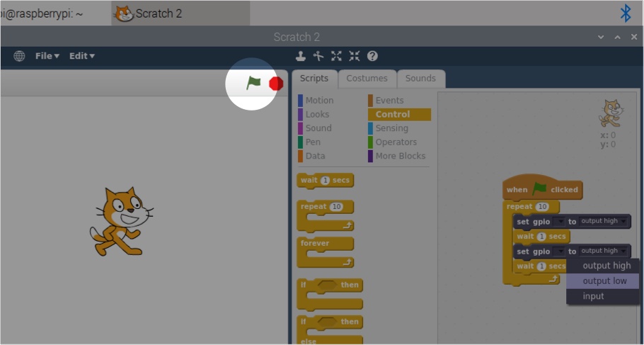
- To see your programme in action , click on the green flag on the top right of the Scratch 2 preview window
Your LED should now be flashing on and off every second. You can experiment with different timings by changing the “wait” timings.
Like what you read? Why not show your appreciation by giving some love.
From a quick tap to smashing that love button and show how much you enjoyed this project.

