Interface to PLCs over Modbus RTU and MQTT using DEBIX Model A with I/O Expansion board (part 2)
The DEBIX Model A based on the Quad-core i.MX 8M Plus processor, along with its DEBIX I/O Module, can communicate with PLCs using Modbus commands over RS485 networks to control the coils or read and write to the PLCs registers. Modbus commands can be transmitted across the network using MQTT as the transport protocol.
In part 1 of this project, we covered setting up the DEBIX board along with the I/O Module and connected it to an RS Pro Logic PLC. We then sent Modbus test commands to control the coils.
Part 2 focuses on interfacing to Ladder Diagram ( IEC 61131-3 ) code running on the PLC to demonstrate reading and writing to the PLCs registers before finalising an MQTT client in Python that can translate MQTT messages into Modbus commands by subscribing to a secure MQTT broker on the network.
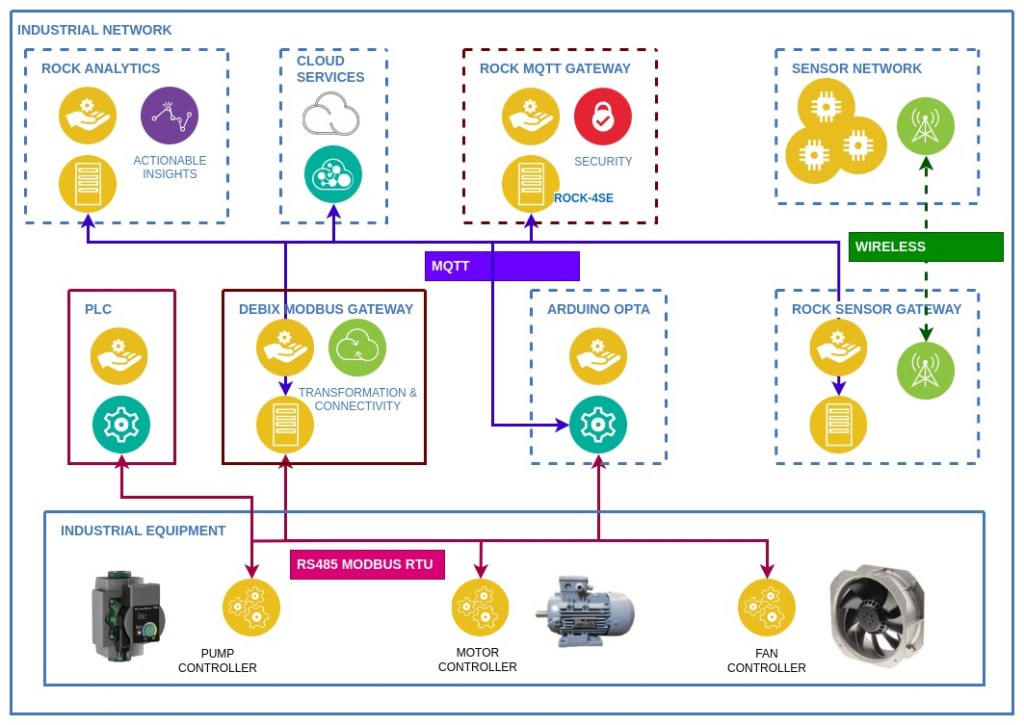
The diagram below illustrates how all these components fit together in our demonstration industrial system:
Author: Peter Milne, engineer and Linux advocate with more SBCs than an Apollo 11 landing craft.
Licence:
Minimal Modbus – Apache License 2.0
Eclipse Paho – Eclipse Public License 2.0
Step 1: DEBIX Model A
The DEBIX Model A board is connected via its 40-pin header to the DEBIX I/O Module, which has 2 RS485 interfaces, one of which is available on the green 7-pin connector on the board edge.
In Part 1 we installed the custom DEBIX OS image, which is based on Ubuntu 20.04. This is configured to export the RS485 port as /dev/ttymxc3 when the I/O Module switches are set accordingly.
A separate 5V / 3A power supply powers the DEBIX and I/O module via its USB-C connector.
Remote access to the DEBIX OS command line is via SSH over Ethernet. It is enabled by default with credentials debix / debix:
$ ssh debix@imx8mpevk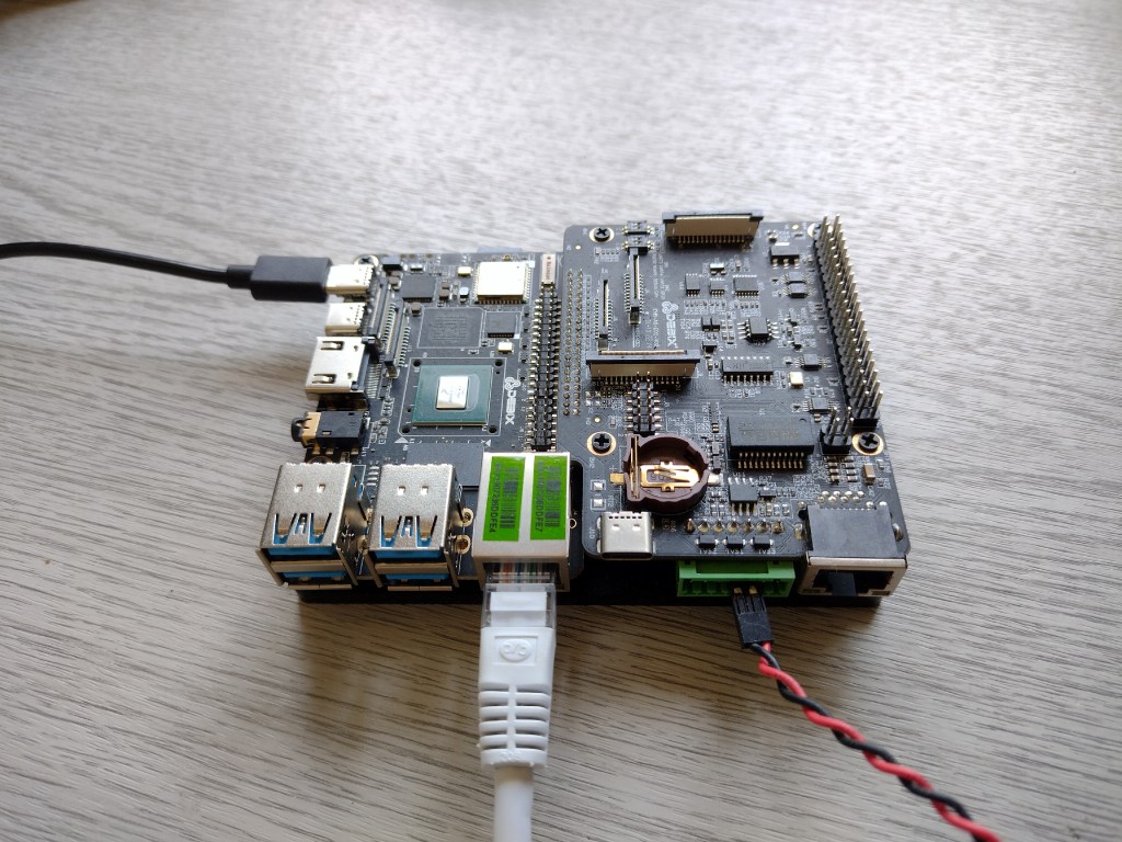
Step 2: PLC
In our Modbus setup, the DEBIX acts as a Modbus client on the RS485 network and is capable of communicating with up to a maximum of 247 Modbus server devices (PLCs, etc.). Here we have it connected to the RS Pro Logic PLC (RS 917-6370) using its associated Communication Module (RS 917-6392).
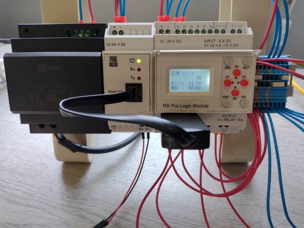
The RS Pro Logic Module is available in 2 variants, 240VAC & 12-24VDC. We are using the DC model for this project (shown on the right) with an RS485 Communication Module (centre) and 24VDC power supply (left).
The PLC has 6 digital inputs (0 – 24V) and 2 analogue inputs (0 – 10V) on the top connectors. It controls 4 isolated relay outputs rated up to 8A at the bottom connectors. Each main module can be chained with up to 3 extension modules with 8 inputs and 4 relays each, giving a possible total of 32 digital inputs, 8 analogue inputs and 16 outputs.
RS485 communication is provided by attaching the PLC to its associated Comms Module using the black cable adapter supplied with the unit. The Comms Module has a half-duplex RS485 interface on its bottom row of connectors which is connected to the DEBIX I/O module.
As well as controlling the coils directly from the DEBIX, we will be executing a Ladder Logic program on the PLC and modifying its registers using Modbus commands sent over MQTT.
Step 3: Circuit
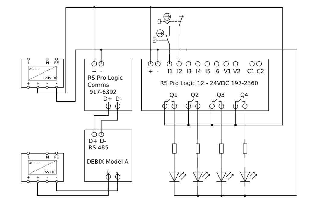
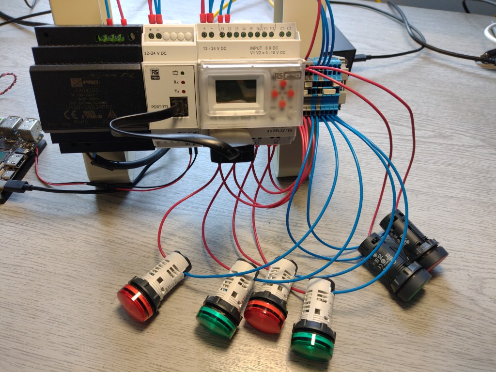
Our test circuit attached to the PLC is very similar to the one used in Part 1, with the addition of a Start button (RS 815-2027) and a Stop button (RS 815-3023) as inputs. The outputs are connected to 24V Schneider LED modules with built-in current limiting resistors; green (RS 610-2691) and red (RS 177-529).
A 24VDC / 4.2A Power Supply (RS 190-4203) provides power for the PLC, Comms Module and LEDs and the whole setup is mounted on a DIN rail.
The DEBIX RS485 connection is via a twisted pair cable from the I/O Module to the connectors on the Comms Module. It is possible to chain the RS485 connections to additional server devices to make up a much larger network.
Here’s the wiring diagram:
And an image of the setup showing the DEBIX (foreground) PLC (centre) and ROCK 4SE broker (right):
Step 4: Minimal Modbus
All the gateway code is written in Python using the Minimal Modbus module to handle the Modbus RTU protocol over RS485.
Installation is straightforward on the Ubuntu-based OS using pip:
$ sudo apt install python3-pip python3-serial
$ pip3 install -U minimalmodbus
Excellent documentation for the module is available here.
Now we are all set up and ready to start developing the gateway code, which we are going to implement using 3 different test clients based on a Command Pattern which will run on the DEBIX. All the tests use the circuit from Step 3.
Firstly, we will implement a client to control the coils directly. This is useful if you want to take over control of the PLC or monitor it from an external application. It will demonstrate Modbus function codes FC01 (Read Coils), FC05 (Write Single Coil) and FC15 (Write Multiple Coils).
Then we will create and load a test Ladder Diagram (LD) program that represents a continuous industrial process running on the PLC. The program uses the Timer functions to flash the LEDs connected to the coils.
This second Python client will read and write the PLCs registers with Modbus FC03 (Read Holding Registers) and FC16 (Write Multiple Registers) whilst the LD program is running. This can be used to change parameters of the LD code running on the PLC without actually altering the logical execution, allowing the extension of existing applications code.
Finally, we create an MQTT client running on the DEBIX that subscribes to a remote MQTT broker. The client will listen for incoming MQTT messages and translate them into Modbus commands to control the PLC.
We will use the secure MQTT broker developed on a ROCK 4SE in this project as our test broker.
The source code for all the examples is available on the OKdo GitHub repository.
Step 5: Command Pattern
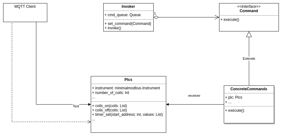
Using the Command Pattern in Python allows us to treat Modbus commands as objects, which can easily be passed as parameters in our clients. It also allows them to be queued up in a buffer so that they are executed in the correct order if there is any network latency.
All concrete commands implement the Command interface, which has a single member function, execute(). The PLC object we want to apply the command to is passed as a parameter along with any data required to execute the command. For example, which coil to turn on or off or which registers to read or write.
Multiple Modbus commands can be combined into a single higher-level command, for example, reading the register settings and storing them before writing new values so that we can restore them back again at a later time.
An Invoker object gets passed commands in its set_command() method, which puts them into a FIFO queue. At some point, the invoker calls its invoke() method, which causes the commands to call their execute() method to be actioned by the receiving object, which in this case is our PLC.
The UML diagram is shown below:
Step 6: Reading & Writing Coils
Let’s start by looking at the Command class and one of its concrete classes, CoilsOnCmd, which turns coils on. The command class is composed of a PLC instance and a list of coils to turn on. It has just one method, execute() which calls the PLCs member function to turn on the coils in the list.
class Command:
    def execute(self):
        raise NotImplementedError

class CoilsOnCmd(Command):
    def __init__(self, plc: Plcs, coil_list: list):
        self.plc = plc
        self.coil_list = coil_list

    def execute(self) -> None:
        if self.plc is not None:
            self.plc.coils_on(self.coil_list)
Now, let’s turn to the Plcs class representing the RS Pro Logic Module. This is initialised with a Minimal Modbus instrument giving it access to the RS485 port and a couple of data members to hold the state of the coils and registers.
There are several member functions that implement each of the commands that the PLC supports, for example the coils_on() function is shown below. These in turn call functions that execute the actual Modbus commands.
class Plcs:
    def __init__(self, instrument: Instrument, num_coils=4):
        self.instrument = instrument
        self.num_coils = num_coils
        self.coil_states = [OFF] * self.num_coils
…
    def coils_on(self, coils: list) -> None:
        self._write_coils(coils, ON)
…
If we look at one of them, the _write_coils() function, it contains the details of reading and writing the Modbus commands. First it reads the current state of all the coils using the method _coils.read(), which uses Modbus function code 01:
    def _coils_read(self) -> list:
        try:
            _coil_states = self.instrument.read_bits(0, self.num_coils, functioncode=1)
            return _coil_states
        except Exception:
	…
and then decides whether to write a single coil or multiple coils depending on the size of the input list. It then saves the new state to the PLC instance if everything is successful.
In the actual code we added logging to output status information which can also be viewed in the terminal.
   def _write_coils(self, coils: list, state: int) -> None:
        _coil_states = self._coils_read()
        for i in coils:
            _coil_states[i] = state
        try:
            if len(coils) == 1:
                self.instrument.write_bit(coils[0], state, functioncode=5)
            else:
                self.instrument.write_bits(0, _coil_states)
        except Exception:
		…
        else:
            self.coil_states = _coil_states[:]
The Invoker is quite simple, it only has two methods. set_command(), which takes a Command object and puts it into a FIFO queue. The invoke() method pulls commands off the queue and calls their execute() method until the queue is empty, making sure that each command is processed in the correct order.
You could add extra functionality here if you need to filter commands or add additional processing for specific reasons.
class Invoker:
    def __init__(self):
        self.cmd_queue = Queue()

    def set_command(self, cmd: Command) -> None:
        self.cmd_queue.put(cmd)

    def invoke(self) -> None:
        while not self.cmd_queue.empty():
            cmd = self.cmd_queue.get()
            cmd.execute()
The client modbus_coil_test.py first of all sets up the Modbus instrument which binds it to the RS485 port on the DEBIX and to the address of the PLC. If there are multiple devices on the RS485 network then you need to create a separate instrument for each one. We then set the baud rate to match the RS Pro Logic Module.
An instance of a Plcs class with the instruments attached is then instantiated along with an instance of the Invoker.
As a test we generate a random list of coils to turn on / off using a helper function and then set the command in the invoker, which puts it into the queue. This is followed up by setting a validation command which checks that the correct coils have been switched.
Finally, the Invoker does its work by executing each command in order.
def main() -> None:
    instrument1 = minimalmodbus.Instrument(PORT, ADDRESS)
    instrument1.serial.baudrate = 9600
    plc1 = Plcs(instrument1, num_coils=4)
    invoker = Invoker()
…
    while True:
        coil_list = gen_coillist(max_coils=4)
        invoker.set_command(CoilsOnCmd(plc1, coil_list))
        invoker.set_command(ValidateCmd(plc1))
        invoker.invoke()
…
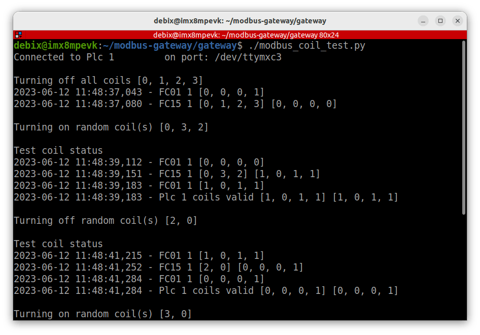
To run the code, make sure the PLC is in the Main Menu mode and not running any code, then execute the test program on the DEBIX in a Terminal within the gateway directory.
debix@imx8mpevk:~/modbus-gateway/gateway$ ./modbus_coil_test.pyThe LEDs should turn on and off according to the commands that have been generated. Here’s the output in the Terminal:
Step 7: Ladder Diagram
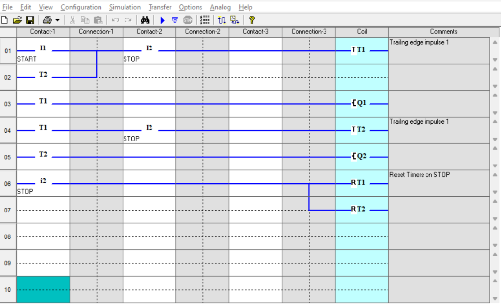
To test reading and writing the registers in a program running on the PLC, we developed a simple Ladder Diagram (LD) code that switches the coils, one after the other. Each coil has a timer which is triggered by the falling edge signal of the previous timer so as the first coil turns off, the next coil turns on.
If we inject new values into the timer parameters we can control the timings of the coils whilst still running the same code logic.
A start switch which is Normally Open (NO) starts the process off and a stop switch which is Normally Closed (NC) stops it at any point by resetting all the timers so the system can’t resume until the start switch is pressed again.
The binary executable is in the ld directory on GitHub and can be flashed to the PLC by installing the free development environment (available from the PLC product page) on a Windows PC, using the USB Programing Cable (RS 917-6395) attached to the RS Pro Logic Module.
The RS Pro Logic software contains a detailed help reference that describes how to do this along with good documentation of the coils, registers and Modbus commands supported by the PLC.
Here’s the LD diagram with just 2 timers (4 are used in the test program) in the RS Logic Pro software:
I1 – Digital Input 1 (Start Switch NO)
I2 – Digital Input 2 (Stop Switch NO)
i2 – Digital Input 2 (Stop Switch NC)
T1 & T2 – Timers triggered by a falling edge signal
RT1 & RT2 – Timer resets
Q1 & Q2 – Relays 1 & 2
Step 8: Reading & Writing Registers
It’s possible to control various parameters for the Timer function in the Pro Logic PLC. These are documented in the help section of the Development Environment.
Each timer is made up of 4 registers. For our example LD program we used timer mode 10, which turns on for a set period when it detects a falling edge signal. So in Python, to set the Holding Registers to 2 seconds, we pass a list of values like this where the first value is the on time in 1/10 second, the second and third values are not used and the final value is the timer mode:
[20, 0, 0, 10]
To create a set_timer() command, we add a new member function to the PLC class that first of all saves the current timer settings and then writes the list of values to the register, starting with the address of the first register for that timer.
The code composes a higher level command out of Modbus FC03 (Read Registers) followed by FC16 (Write Registers):
   def timer_set(self, start_address: int, values: list) -> None:
        self._timer_save(start_address)
        self._write_registers(start_address, values)
Here’s the function that saves the register values using Modbus function FC03:
   def _timer_save(self, start_address) -> None:
        try:
            timer = {start_address: self.instrument.read_registers(start_address, number_of_registers, functioncode=3)}
        except Exception:
		…
        else:
            self.timer_states.update(timer)  # Stash timer values
And the function that writes the registers with Modbus FC16:
   def _write_registers(self, start_address: int, values: list) -> None:
        try:
            self.instrument.write_registers(start_address, values)
        except IOError:
            …
We also need to add a TimerSetCmd command class that can be invoked:
class TimerSetCmd(Command):
    def __init__(self, plc: Plcs, start_address: int, values: list):
        self.plc = plc
        self.start_address = start_address
        self.values = values

    def execute(self) -> None:
        self.plc.timer_set(self.start_address, self.values)
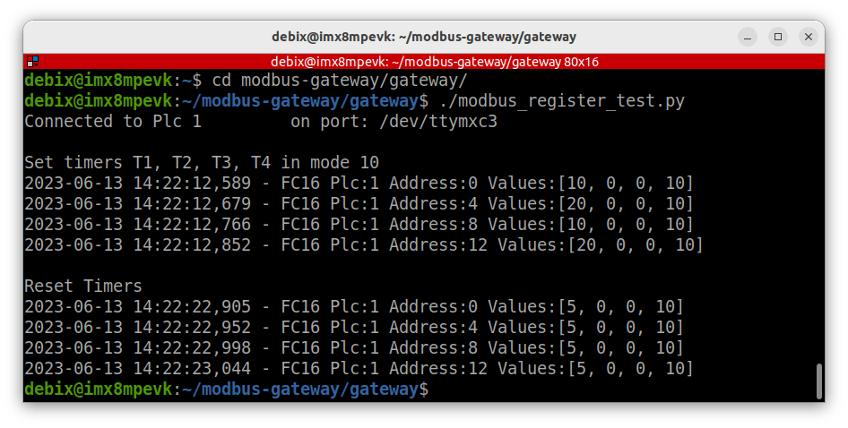
Finally, the modbus_register_test.py client code is very similar to the previous client. The usual objects are created, then we set the commands to change all 4 timers with the TimerSetCmd() and execute these. After a short delay we set them back to their original values with ResetTimerCmd().
def main() -> None:
    instrument1 = minimalmodbus.Instrument(PORT, ADDRESS)
    instrument1.serial.baudrate = 9600

    plc1 = Plcs(instrument1, num_coils=4)
    invoker = Invoker()

    invoker.set_command(TimerSetCmd(plc1, 0, [10, 0, 0, 10]))  # T1
    invoker.set_command(TimerSetCmd(plc1, 4, [20, 0, 0, 10]))  # T2
    invoker.set_command(TimerSetCmd(plc1, 8, [10, 0, 0, 10]))  # T3
    invoker.set_command(TimerSetCmd(plc1, 12, [20, 0, 0, 10]))  # T4
    invoker.invoke()
    time.sleep(10)
    invoker.set_command(ResetTimersCmd(plc1))
    invoker.invoke()
Make sure that the LD code is running on the PLC and press the Start button. The LEDs will blink for ½ second in a continuous sequence. Then run the test program on the DEBIX in a Terminal.
debix@imx8mpevk:~/modbus-gateway/gateway$ ./modbus_register_test.pyThe LEDs will blink rate will now alternate for 1 and 2 seconds before returning to their previous settings after the delay.
Here’s the output in the Terminal:
Step 9: Modbus / MQTT Client
Our final client turns the DEBIX into an MQTT / Modbus gateway that can execute Modbus commands sent over the network as MQTT messages.
In a previous project, we set up a ROCK 4SE to act as a secure MQTT server which we will use for this part of the testing. Configure it to allow anonymous access on port 1883 and client certificates on port 8883, just to make testing a bit easier.
The Eclipse Paho Python Client provides a client class with support for MQTT v5.0, MQTT v3.1.1, and v3.1 on Python 3. It also provides some helper functions to make publishing one off messages to an MQTT server very straightforward, so we will use this as a basis to add MQTT support to our Modbus code.
It can be installed on the DEBIX OS from the repo using:
$ sudo apt install python3-paho-mqttThere is excellent documentation on PyPi and example code in the project’s GitHub repo.
Before we look at the client code, we need to discuss how to implement the MQTT messages. MQTT uses a Topic Path and a message Payload. For our system we have chosen to encode the PLC name that we want to communicate with in the topic path and the coils or register addresses encoded as a JSON payload in the message.
To send a Coils On command to our first PLC we set the following topic path:
test/plc1/coils_onAnd we send the list of coils to turn on as a JSON payload in the message. This example will act on coils Q2 & Q3 (Q1 is at address 0):
{"coils":[1,2]}So, to turn on Coils Q2 & Q3 on the RS Pro Logic PLC, we would publish the following MQTT message from a Mosquitto client to our ROCK broker:
$ mosquitto_pub -h rock-4se -t "test/plc1/coils_on" -m '{"coils":[1,2]}'This scheme maps very cleanly to the Paho callback mechanism in the final client code mqtt_client.py.
Here we set up the Modbus connection and invoker objects as before, but we add in a dictionary of PLC objects to enable a string lookup:
instrument1 = minimalmodbus.Instrument(PORT, ADDRESS)
instrument1.serial.baudrate = BAUDRATE
plc1 = Plcs(instrument1, num_coils=4)
plcs = {'plc1': plc1}  # Dict of plc instances
invoker = Invoker()
Then we define callback methods that set the commands in the Invoker, defined by the topic path and payload. The JSON payload is unpacked as a Python dictionary and a helper function looks up the PLC object to pass to the command object in the set_command() method.
def plc_coils_on(mosq, obj, msg):
    payload = json.loads(msg.payload)
    invoker.set_command(CoilsOnCmd(plc_lookup(msg.topic), payload['coils']))
Here’s the function that obtains the PLC object. It splits the Topic Path down into a list of strings and uses the ‘plcn’ part of the path to lookup and returns the correct PLC object from the dictionary:
def plc_lookup(topic: str) -> Plcs:
    sub_topic = topic.split('/')
    try:
        return plcs[sub_topic[1]]
    except KeyError:
        return None
A separate callback needs to be defined for each supported command. They are mapped in the main() function, where you can see the topic path relating to each callback method. The ‘+’ in the topic path does the mapping from ‘plc1’, ‘plc2’ etc.
There’s also a catchall callback at the end on_message, in case any received topics don’t match:
mqttc.message_callback_add(TOPIC_ROOT + "/+/coils_on", plc_coils_on)
mqttc.message_callback_add(TOPIC_ROOT + "/+/coils_off", plc_coils_off)
mqttc.message_callback_add(TOPIC_ROOT + "/+/timer_set", plc_timer_set)
mqttc.message_callback_add(TOPIC_ROOT + "/+/timer_reset", plc_timer_reset)
mqttc.on_message = on_message
It’s quite easy to set up a secure client connection based on the client ID and the necessary certificates and key. This was covered in detail in the ROCK MQTT Server project.
The trick here is to copy the correct certificates onto the DEBIX and make sure you provide the right file paths. Here they have been placed relative to the gateway directory in the ‘certs’ sub-directory.
After creating the client and setting the certificates, we connect to our broker on secure port 8883 and then subscribe to any topic path beginning with ‘test’. Paho handles all the authentication for us:
def main() -> None:
    mqttc = mqtt.Client('client01')  # CLIENT_ID
    mqttc.tls_set(
        ca_certs='certs/root_ca.crt',  # ROOT_CERT
        certfile='certs/client01.crt',  # CLIENT_CERT
        keyfile='certs/client01.key'  #CLIENT_KEY
    )
…
    mqttc.connect('rock-4se', 8883, 60) # BROKER
    mqttc.subscribe("test" + "/#", 0)  # TOPIC_ROOT
Tip: Test that you can get secure access using mosquitto_pub & mosqitto_sub then copy the certificates to your certs directory on the DEBIX.
The final part of main() starts a loop in a separate thread which keeps the MQTT connection alive and then we call the invoker in a loop forever. This will invoke any commands as soon as they are received. Pulling them off the queue and running their execute() method.
    mqttc.loop_start()
    while True:
        invoker.invoke()
Make sure that your MQTT broker is up and available on your network and that the PLC is running the LD program, then run the mqtt_client.py on the DEBIX:
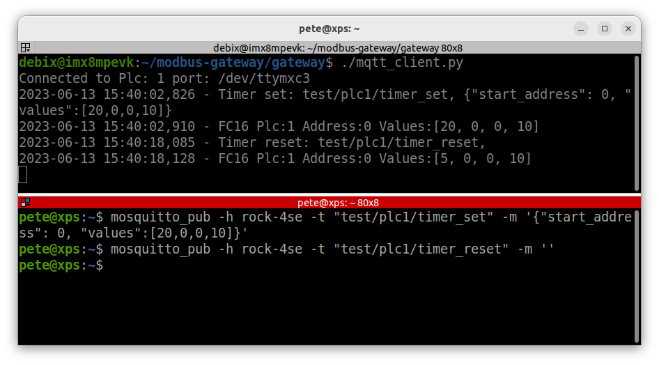
debix@imx8mpevk:~/modbus-gateway/gateway$ ./mqtt_client.pyNow open a Terminal on any network host with Mosquitto Clients installed and send some messages, for example to set timer T1 (address 0) to 2 seconds:
$ mosquitto_pub -h rock-4se -t "test/plc1/timer_set" -m '{"start_address": 0, "values":[20,0,0,10]}'Then issue another command with an empty payload to reset it:
$ mosquitto_pub -h rock-4se -t "test/plc1/timer_reset" -m ''Here’s the output in the Terminal:
Step 10: Systemd
The final step is to create a systemd service unit for the MQTT client so it starts up when the DEBIX boots.
Add the following service unit to /etc/systemd/system:
[Unit]
Description=Modbus Gateway
After=network-online.target
Wants=network-online.target

[Service]
User=debix
Group=debix
Restart=always
WorkingDirectory=/home/debix/modbus-gateway/gateway
ExecStart=/home/debix/modbus-gateway/gateway/mqtt_client.py
TimeoutStartSec=0
RemainAfterExit=yes

[Install]
WantedBy=multi-user.target
Now start the gateway service:
$ sudo systemctl daemon-reload
 $ sudo systemctl start gateway.service
All being well your MQTT client should be listening on port 8883 for incoming messages.
Congratulations you now have a working MQTT / Modbus gateway that can communicate with your PLCs!
Summary
In this project, we have shown how to set up the DEBIX Model A board and I/O Module and connect it to a PLC over an RS485 interface and implement a working MQTT / Modbus gateway client.
We demonstrated controlling an RS Pro Logic PLC directly by reading and writing to its coils, and we showed how to modify the timer registers on a running LD program.
Both of these techniques can be used to create new PLC applications or extend existing infrastructure in innovative ways that you control, opening up a world of opportunities for industrial automation, building control and agri-tech solutions.
References:
![]()

Let’s invent the future together
What’s your challenge? From augmented reality to machine learning and automation, send us your questions, problems or ideas… We have the solution to help you design the world. Get in touch today.
Like what you read? Why not show your appreciation by giving some love.
From a quick tap to smashing that love button and show how much you enjoyed this project.

