Interface to PLCs over Modbus RTU using DEBIX Model A with I/O Expansion board (part 1)
In this project, we are using the DEBIX Model A along with its DEBIX I/O board to send Modbus commands to a PLC over RS485.
We take you through setting up the DEBIX board with the I/O module and build a test circuit for the PLC using industrial-grade components and start to develop a Python application for the Gateway.
It’s the second one in a series of projects that showcases ROCK boards and other SBCs in an industrial context, demonstrating innovative IIoT solutions that can integrate into existing industrial automation, smart agriculture and building management infrastructure or form the building blocks for new solutions.
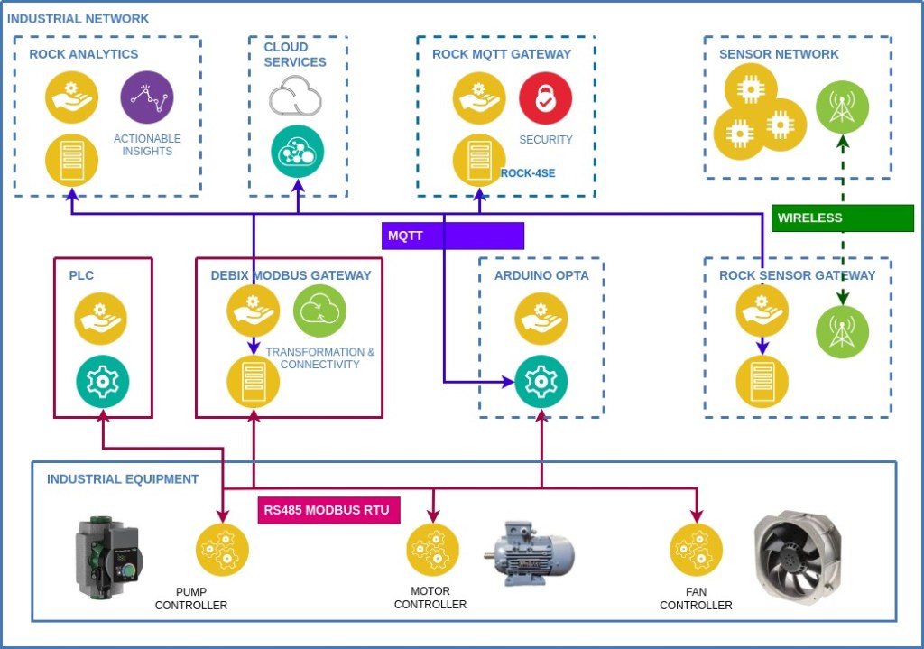
In the first project, we built a secure MQTT Gateway based on the ROCK 4SE, so now we need a solution to translate MQTT messages into Modbus commands to control and monitor PLCs and other devices on the network that understand Modbus protocol.
When the Gateway is finished, we will be able to send MQTT commands through the ROCK Gateway to the Modbus client running on the DEBIX Gateway, which will be capable of controlling and monitoring a series of PLCs on an RS485 network.
The diagram below shows how the components fit together in our demonstration system.
Author: Peter Milne, engineer and Linux advocate with more SBCs than an Apollo 11 landing craft.
Step 1: Debix Model A
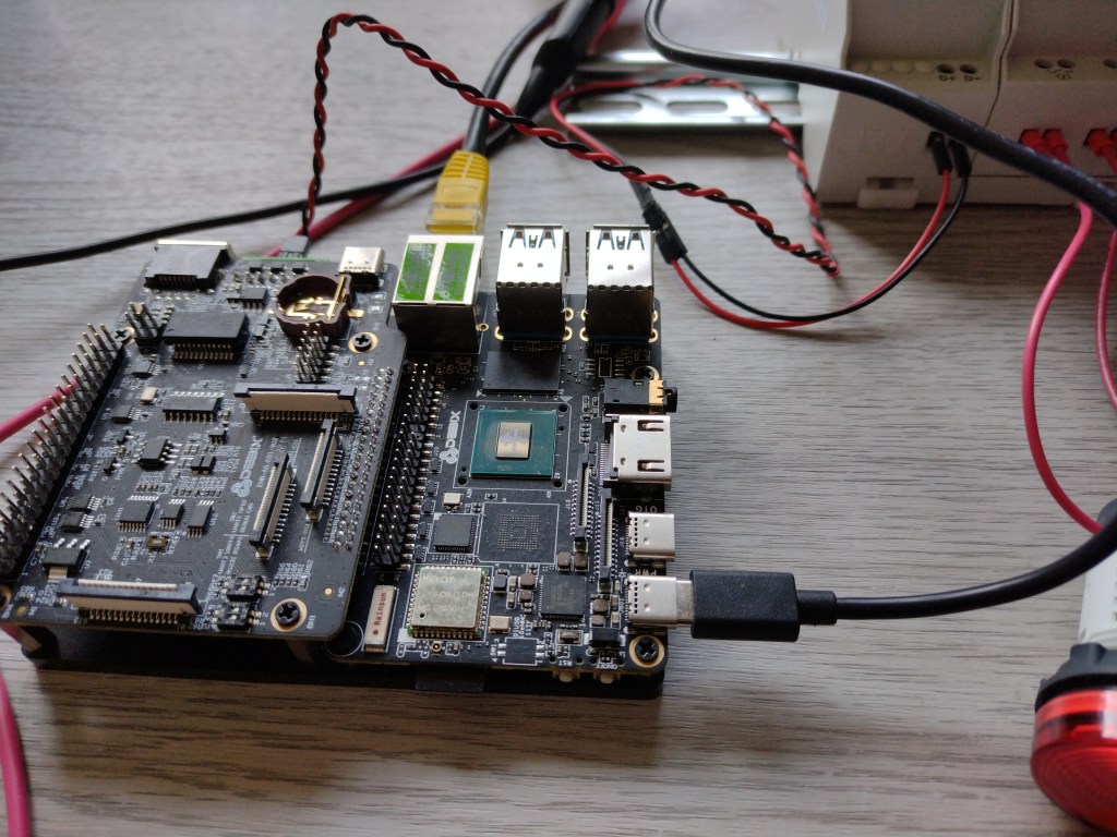
The DEBIX Model A, along with its I/O Module, makes a capable development platform for prototyping and deploying MQTT / Modbus gateways.
Based on the Quad-core i.MX 8M Plus processor, it has plenty of capacity to handle the protocol translation required for this application. The associated I/O module provides a convenient solution for handling the physical interface for RS485, RS232 and CAN, allowing it to act as the Client in our Modbus RTU network.
Connectivity is provided via 2 x Gigabit Ethernet ports, one on the SBC and the other on the I/O module, with POE available on the latter. Dual-band Wifi and Bluetooth 5.0 is also an option.
Power requirements are USB-C 5V / 3A to the main board, which also powers the I/O board. This provides a convenient Serial Console via its USB-C connector. There’s also an RTC with battery backup and a host of camera and display peripherals that we are not using in this project.
We covered setting up the DEBIX Model A with the I/O board in detail in our Getting Started Guide with DEBIX.
Schematics and Datasheets are available on the product page: https://www.okdo.com/p/debix-model-a-i-o-board/
DEBIX provides its own spin of Ubuntu 20.04, a Yocto image with 5.10 kernel, Android 11 and Win10 IoT Enterprise. We will be using the Ubuntu image for this project, but once you have developed the firmware, you could add it to the Yocto image, which may be more suitable for actual production use.
- Visit the DEBIX Download page and install the Ubuntu image to a high-quality microSD card
- Attach the board to your network with an Ethernet cable and boot the board.
- SSH in from a remote terminal with default hostname imx8mpevk / username debix / password debix secure the password and run the usual checks.
$ ssh debix@imx8mpevkThat gives us the basic setup for the gateway application. We will add the required packages in the next steps.
Step 2: PLC
For our PLC, we are using the RS Pro Logic Module (RS 917-6370) and the associated RS485 Communication Module (RS 917-6392). These come in 240VAC & 12-24VDC variants, and we are using the DC models in this project.
The PLC has 6 digital and 2 analoge (0 – 10V) inputs and controls 4 relay outputs rated up to 8A. Each main module can be chained with up to 3 extension modules with 8 inputs and 4 relays each, giving a total of 32 digital inputs, 8 analogue inputs and 16 outputs.
RS485 connectivity is provided by the additional Comms Module, which comes with a TTL cable to attach to the Logic Module (Not shown in the image). It supports Half-duplex RS485 via the D+ / D- connectors on the bottom of the unit. The module acts as a Server on the Modbus network.
Remote programming using Ladder Logic is done using a Windows 10 (only) application and an additional custom TTL programming cable (RS 917-6395). You can download the free programming environment from the RS Product Page.
Documentation for the PLC and Comms unit is excellent but hidden away in the app’s help system, so you will need a Windows PC to access it. A section on Modbus commands and addressing is included, along with examples.
- Connect the Logic Module to your PC with the programming cable and apply power. Then use the software to configure the Device ID to 1 and the Baud rate to 9600.
- Disconnect the programming cable and connect the Comms Module to the Logic Module with the supplied TTL connector cable.
Step 3: Circuit
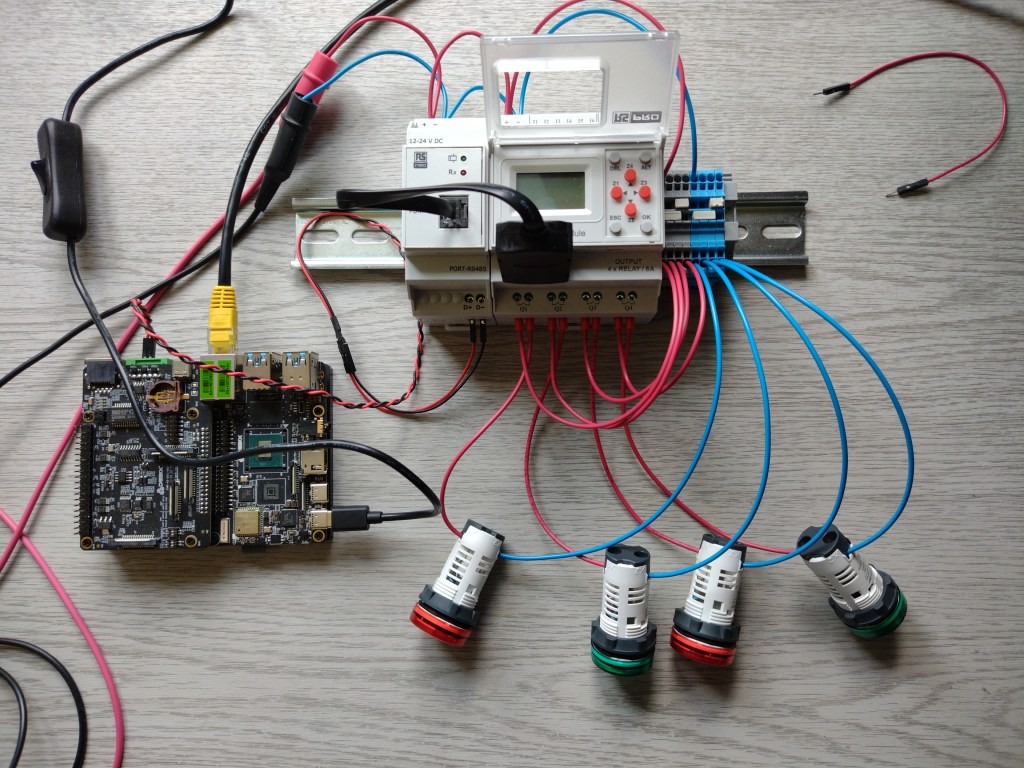
In order to test our DEBIX Gateway, we will need a test circuit to prove that everything is working as expected. We built a simple circuit using 4 x 24V Schneider Electric LED panel lamps (Green RS 610-2691 & Red 177-529) connected between the output relays and the negative supply rail of a bench power supply. The LEDs represent real equipment controlled through the relays.
We don’t need any inputs at this stage, as we will be controlling the coils remotely via firmware running on the DEBIX Gateway.
Here’s the wiring diagram:
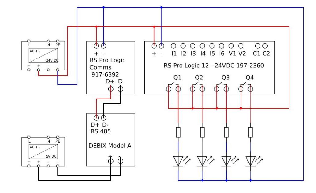
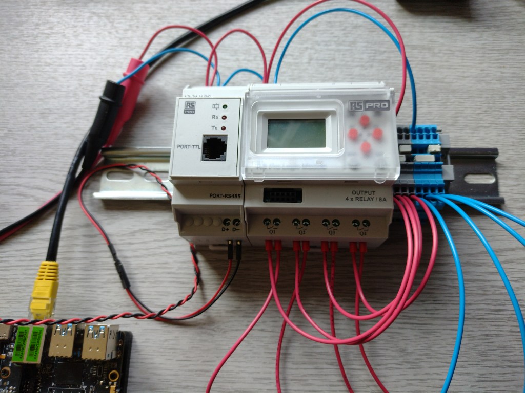
This is the setup on my bench with the DEBIX unit attached. The DIN rail connectors form common Power (Grey) and Ground (Blue) rails using jumpers. 12V power is supplied from a Bench Power Supply for the PLC and Comms unit. The DEBIX is supplied from a separate 5V / 3A Power Supply.
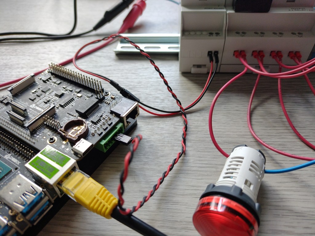
This image shows the TTL connector in use. RS485 details are in the next section:
Step 4: RS485
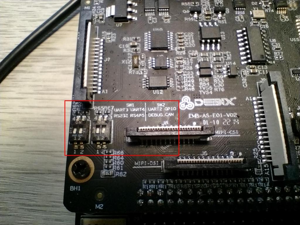
Configuring the DEBIX I/O module for RS485 comms is simply a case of setting the jumpers on SW1 & SW2. These are located close to the MIPI-CSI connector, and the settings are marked on the silk screen.
Set the I/O board to use RS485 and DEBUG port by setting SW1-2 OFF and SW2-1 OFF, the other switches can be set to OFF as shown in the image:
| Position | SW1-1 | SW1-2 | SW2-1 | SW2-2 |
| ON | ||||
| OFF | N/A | RS485 | DEBUG | N/A |
Using a twisted pair cable, connect pins 3 & 4 of the Green connector on the DEBIX I/O module to the D+ / D- terminals on the Comms module. RS485 uses a differential signal pair and can be used over long distances of up to 1000m or so, depending on data rates.
Modbus commands can address up to 247 servers, so our single DEBIX Gateway is capable of controlling a very large number of devices along a single RS485 network.
| DEBIX I/O Connector | RS485 Comms Module |
| Pin 3 (RS485 A) | D+ (RS485 A) |
| Pin 4 (RS485 B) | D- (RS485 B) |
These settings make the RS485 port appear as /dev/ttymxc3 in the DEBIX OS.
Step 5: Minimal Modbus
Searching PyPi.org for Modbus returns over 200 projects to choose from if you want to program with Python. We’ve selected Minimal Modbus because it’s a well-documented and active project with support for Modbus RTU and an Apache 2.0 licence. It’s also used in some commercial PLC controllers and Gateway products. See the project details here.
The module is not available as a package in the Ubuntu repo, so we need to install a couple of dependencies first.
- Install Pip and PySerial
sudo apt install python3-pip python3-serial
- Now install Minimal Modbus from PyPi:
pip3 install -U minimalmodbus
First-class documentation is available on MinimalModbus.
The source code is on GitHub, which is worth investigating if you want to gain a better understanding of how it works and for issues and PRs.
Step 6: Modbus Test
Now that we have everything connected up and the software in place, it’s time to write a smoke test to make sure everything is working as expected.
First, we have to import the minimalmodbus module and do some setup code. The PLC object is instantiated as a Modbus instrument by passing the port and device ID to minimalmodbus. We also have to set the baud rate as our PLC runs at 9600.
Minimal Modbus uses decimal addressing, so on the RS Pro Logic module, the first coil is at address 0. The code sets the coil on by writing the value bit high using Modbus function code 15. It then reads the coil status using function code 1 before setting the bit low again. It then goes to the next coil address and so on, looping after the last coil.
Enter this Python script into a file called smoke_test.py
import minimalmodbus as mm
from time import sleep

ON = 1
OFF = 0

plc = mm.Instrument('/dev/ttymxc3', 1)
plc.serial.baudrate = 9600

while True:
    # Toggle outputs Q1 - Q4 in sequence
    for coil in range(0, 4):
       plc.write_bit(coil, ON, functioncode=5)
        print(f'Q{coil + 1}, {plc.read_bit(coil, functioncode=1)}')
        sleep(1)
       plc.write_bit(coil, OFF, functioncode=5)
        print(f'Q{coil + 1}, {plc.read_bit(coil, functioncode=1)}')
        sleep(1)
I write the code in my editor and then scp it from a Terminal over to the DEBIX or you can do it directly on the DEBIX board from a remote terminal or using the Serial Console:
scp smoke_test.py debix@imx8mpevk:~/Then open another Terminal and SSH in to the DEBIX and run the smoke test:
ssh debix@imx8mpevk
python3 smoke_test.py
All being well, you should get a nice sequence of lights flashing with the status output in the Terminal, Something like this, proving that we can send Modbus commands to the PLC and read the status of its registers over our RS485 connection:
Summary
In this project, we have shown how to set up the DEBIX Model A board and I/O Module and connect it to a PLC over an RS485 interface. We also demonstrated a simple circuit to use in testing out Minimal Modbus read and write commands that control and monitor coils on a PLC using Python.
In the next project, we will complete the Gateway by building a Python client that will run on the DEBIX to translate MQTT commands coming from our ROCK Gateway into Modbus commands. We will show how to interact with a Ladder Logic program running on the PLC to monitor and control its registers to extend the functionality of existing PLC systems as well as control them directly.
References:
![]()

Let’s invent the future together
What’s your challenge? From augmented reality to machine learning and automation, send us your questions, problems or ideas… We have the solution to help you design the world. Get in touch today.
Like what you read? Why not show your appreciation by giving some love.
From a quick tap to smashing that love button and show how much you enjoyed this project.

