We’re no geniuses. (No, really.) But we do know a thing or two about setting up Flick. Mainly because we’ve done it, like, a zillion times. And since it’s the neatest piece of kit ever invented, we know lots of you Out There would love to get on board (see what we did there?) with it. So we thought we’d share our secrets, free of charge. Though you can buy us a flat white if ever we meet.
If you’ve been living on planet Zog, we’d better explain – Flick boards are add on boards for the Raspberry Pi which bring 3D tracking and let you control your I2C enabled devices with the wave of a hand. Flick achieves this conjuring trick by using technology which lets the PCB detect your gestures from up to 15cm away – in 3D space. How cool is that?
Right, let’s roll up our sleeves and get to work.
There are three flavors of Flick – HAT, Zero and Large. We’re going to show you how to put each of these boards together and how to set them up in their cases. We’ll then chat through some of the most common problems and questions.
For starters, follow the link to the board you’re interested in:
Or skip to the FAQ section if you are having troubles.
Flick HAT
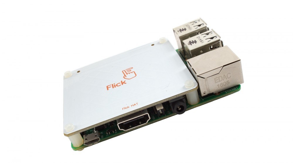
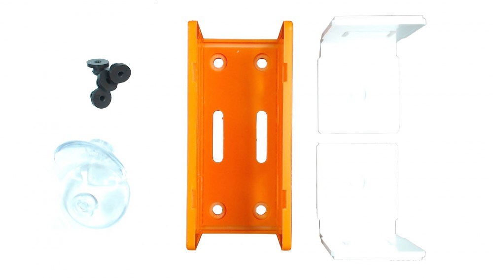
First, let’s look at the Flick HAT board. Take a peek inside the box and you should find:

- 1 Flick HAT
- 8 plastic bolts
- 4 plastic spacers
- 3 stickers
- 2 info cards
Prep your Pi
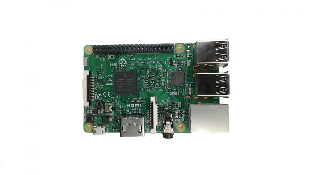
OK, let’s start at the beginning (apparently it’s a very good place to start) by unpacking our Raspberry Pi.
Next we screw-in the spacers in like so (holding them in place with plastic bolts from beneath the Pi):
![]()
Attach Flick HAT
Now, with trembling hands, we remove the Flick HAT from its anti-static bag:
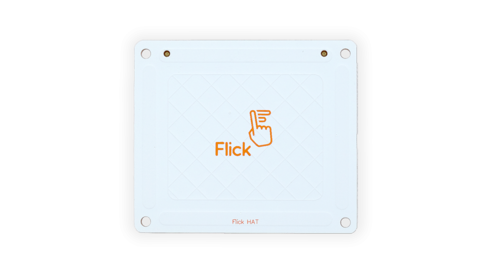
Mmm…nice. Now fix the Flick HAT on top of the Raspberry Pi by gently pushing the female header onto the Raspberry Pi male header until it clicks into place.
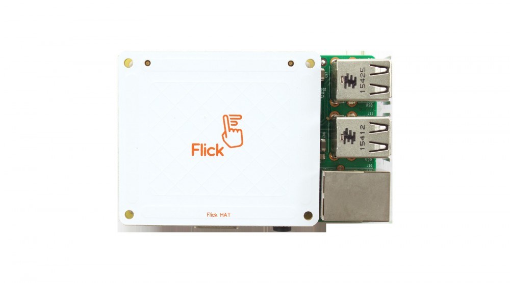
Voila! If you’ve got the case, skip to the next bit where we’ll show you how to house your Flick HAT.
Finally, screw-in the last four plastic bolts to hold your Flick Hat in place…
And now (drum roll please) your Flick HAT is all set to be used.
Assembling the case
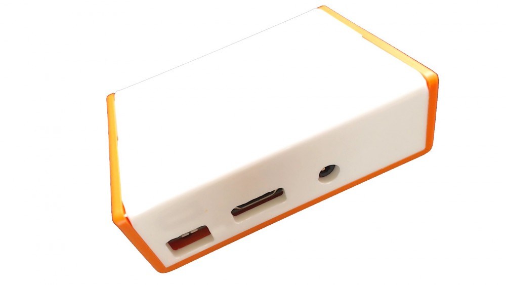
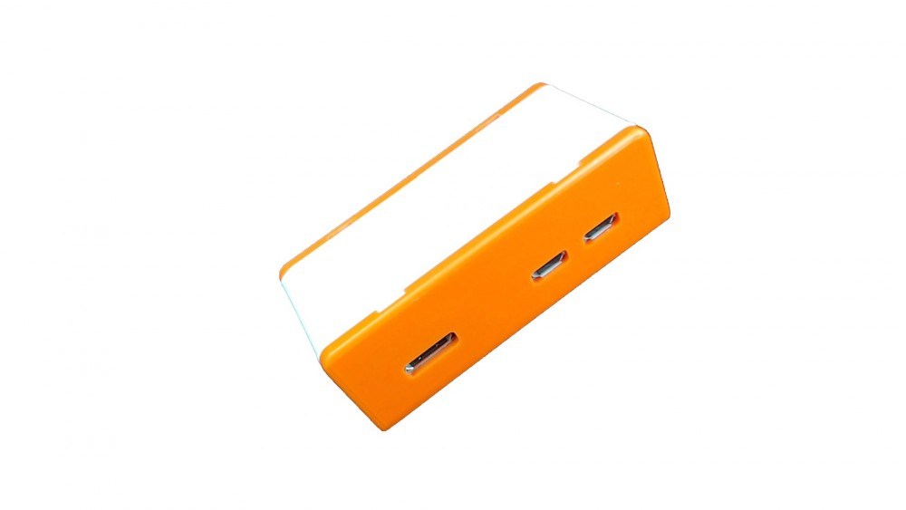
The Flick HAT Case is the perfect housing for the Flick HAT.
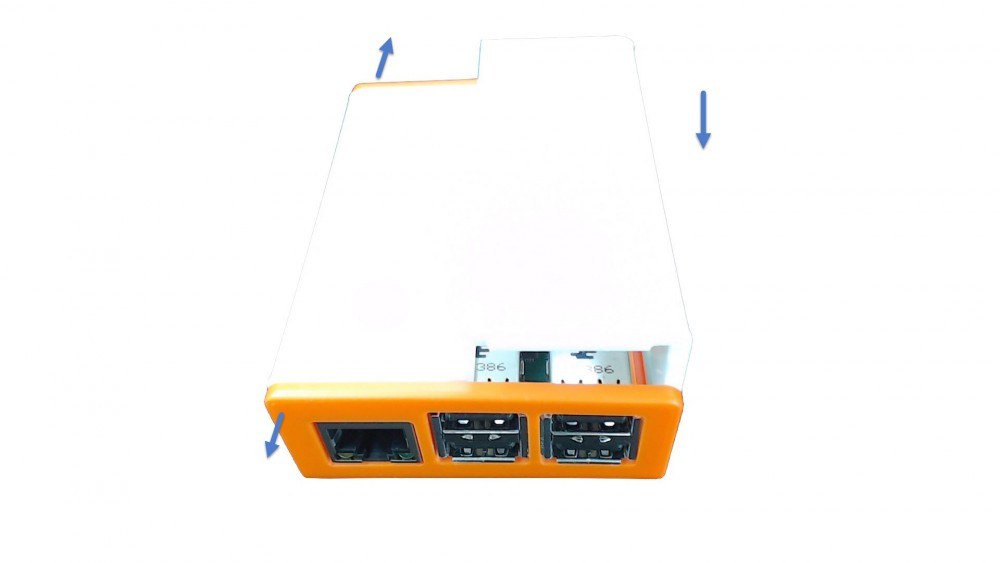
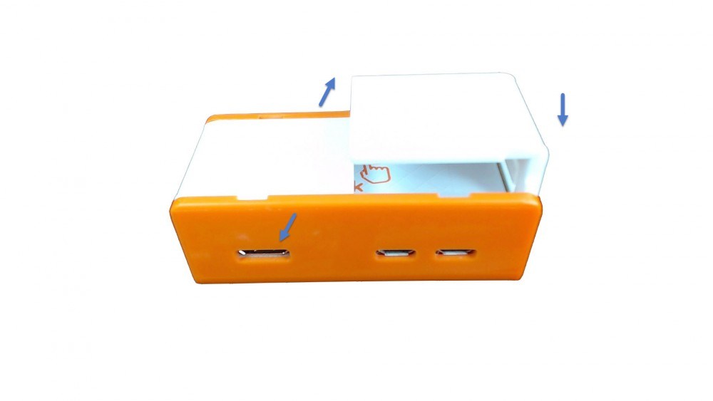
Just remove the protective plastic bits, then gently pull out the two sides of the bottom part of the case to unhook the top…
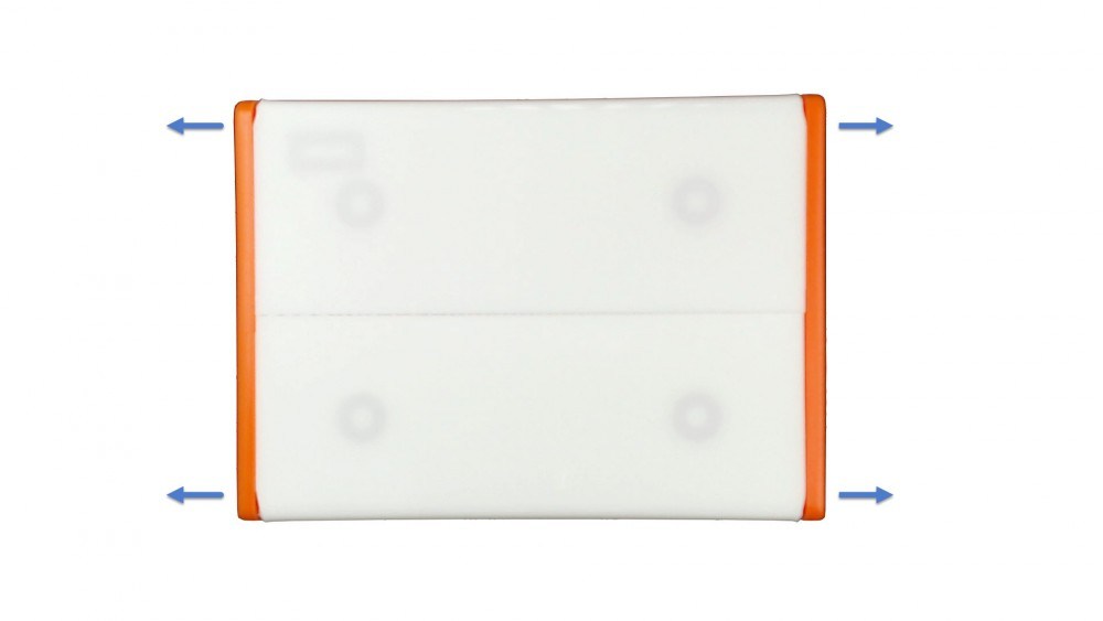
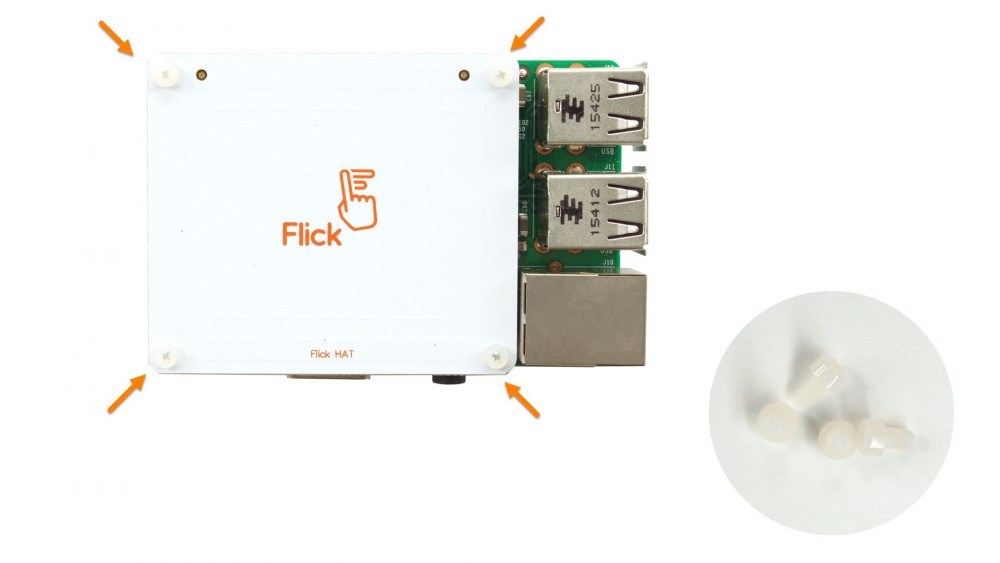
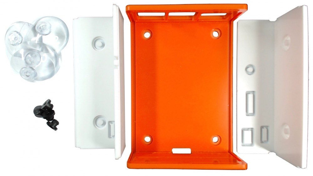
This let us detach the top cover and take the case apart. Inside we found four rubber feet and four suction cups:
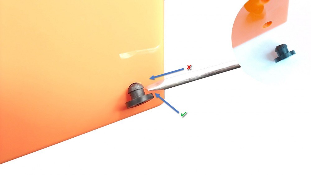
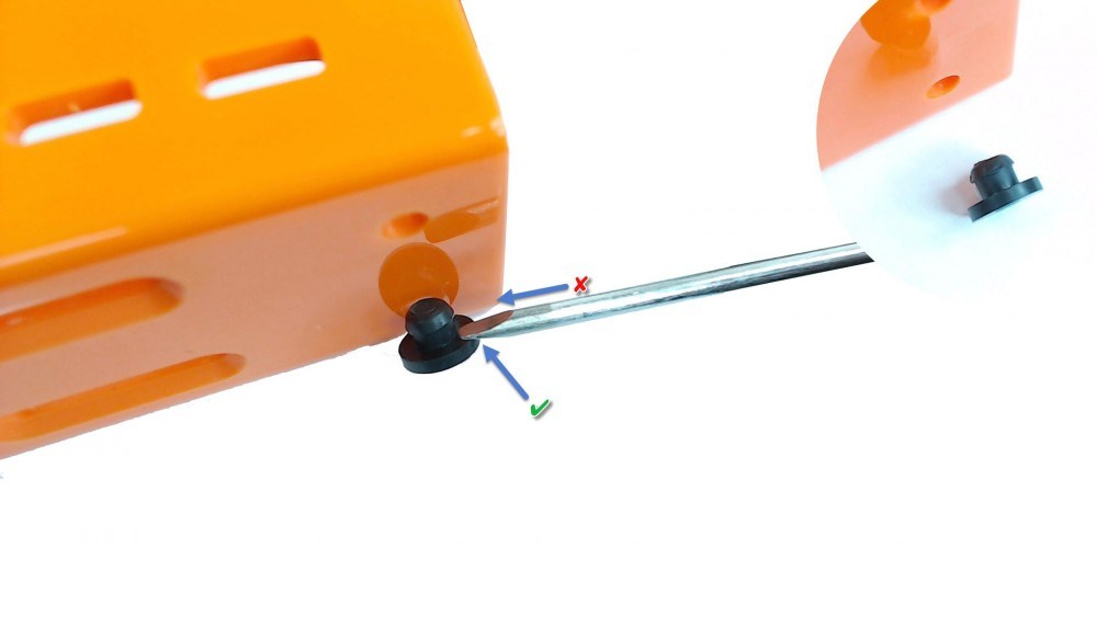
We then pushed and twisted each rubber foot through one of the four holes on the bottom of the case. To help with this little task, we used a small screwdriver to tuck the top part of the feet inside the hole (being careful not to slice through the feet – derr):
Add your Pi
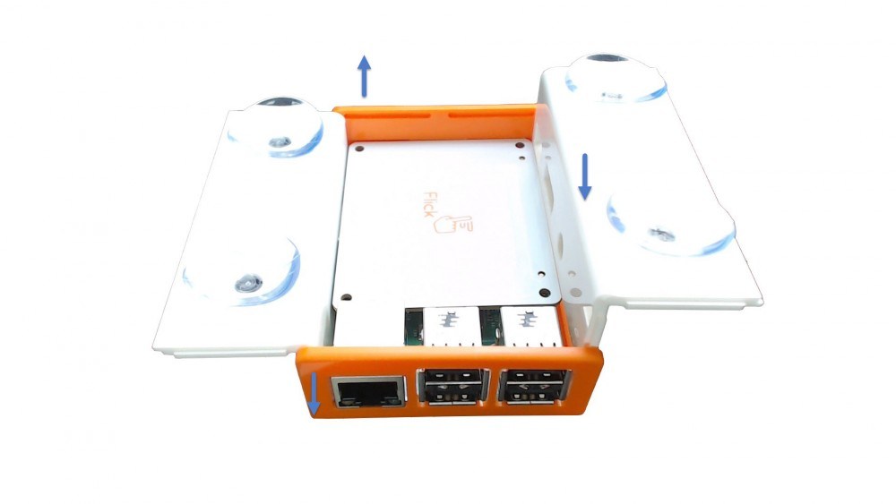
We then slipped the Raspberry Pi and Flick board into the bottom part of the case by first placing the USB connectors in. The PCBs of the two boards should be aligned within the grooves of the panel:
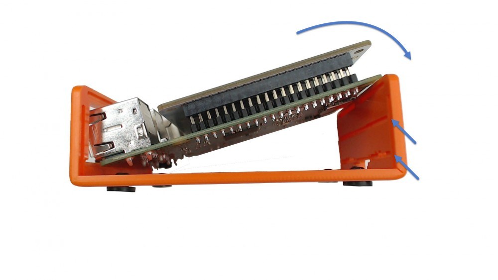
After they’re both rotated into position, our Raspberry Pi and Flick board were sitting ever so nicely in the base of the case.
Finishing up
Stop. Right. Now.
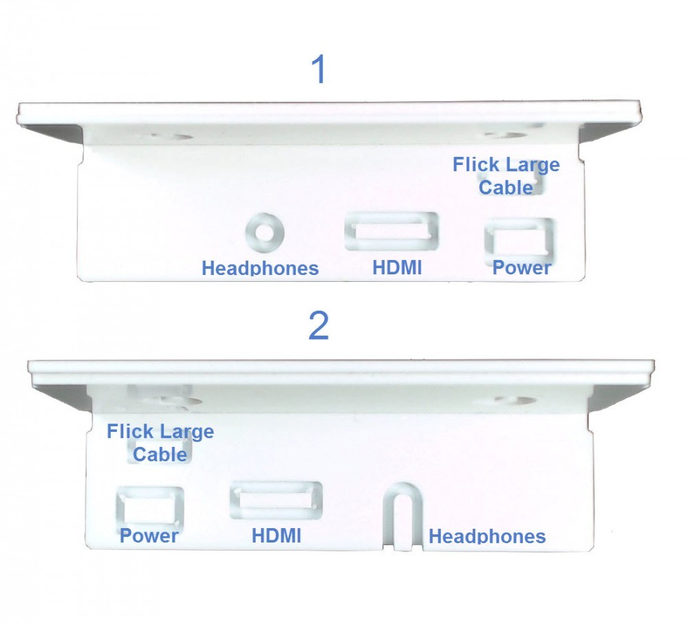
Before we go on, we need to think long and carefully about which knock outs need to be removed from which of the two panels.
If you want to be able to close the case – you need to remove the knock outs from panel 1.
Or if you want to keep the case open, remove the knock outs from panel 2.
And here’s another thing to think about: ONLY remove the knock outs labelled ‘Headphones’, ‘HDMI’ and ‘Power’.
No we happen to love our suction cups, but if you’re not planning to use them and just want to close the case, read straight on. If suction cups float your boat, skip the next bit and go onto the part about assembling with suction cups.
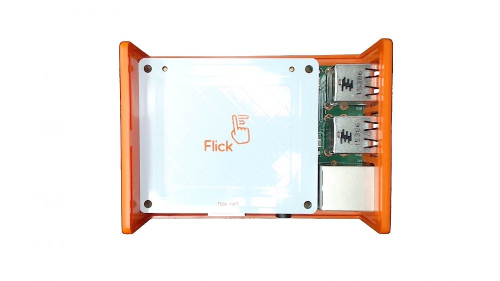
So to close the case, gently flex the sides of the bottom part of the case so you can create space to slot the white panel back in:
Now your Flick HAT is poised for action.
Suction cup lover? Here’s how to put your case together incorporating these little suckers.
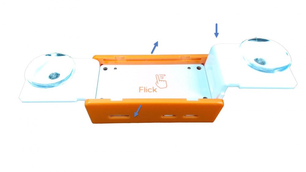
We installed the suction cups on the two white panels.
(If you’re not sure how to remove the knock outs for the suction cups, check out the FAQs at the end of this piece.)
Now we gently flexed the sides of the bottom part of the case so we could slot the white panels back in.
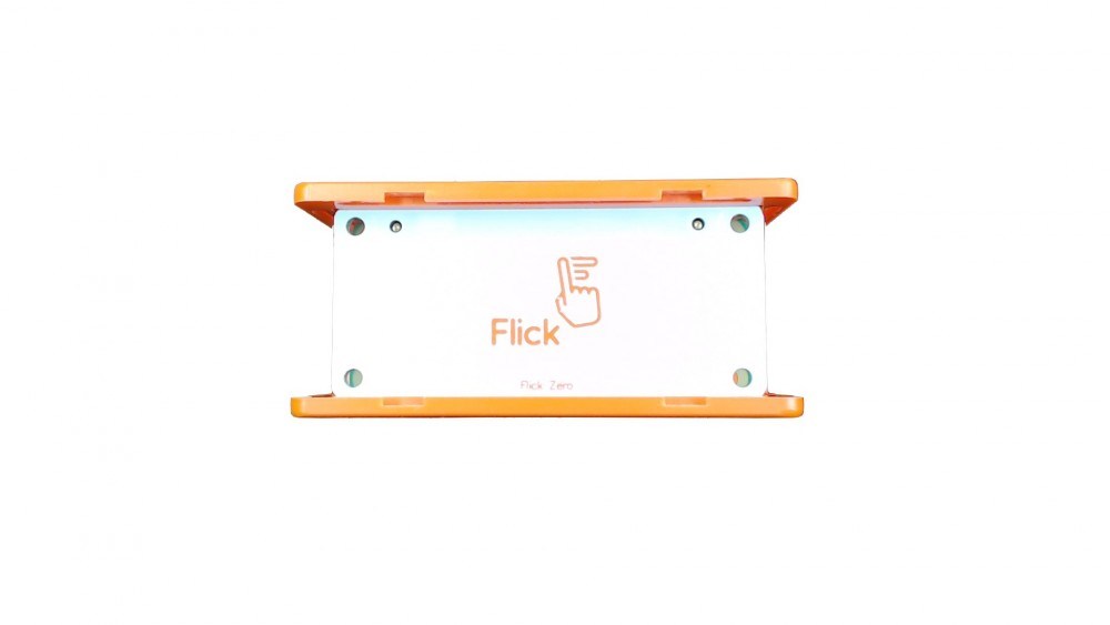
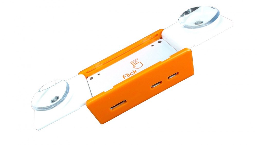
Ta-daaah! Our Flick HAT is ready to be used.
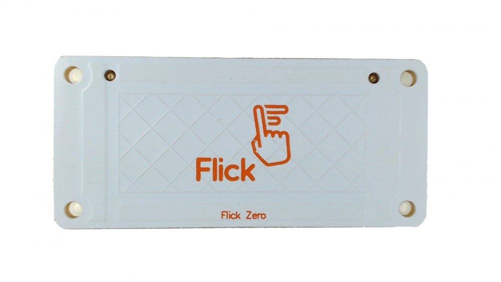
Flick Zero board
OK, now for the Flick Zero board.
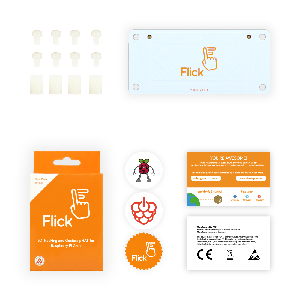
Taking the same approach as above, we started by unpacking our kit, which consisted of:
- 1 Flick Zero
- 8 plastic bolts
- 4 plastic spacers
- 3 stickers
- 2 info cards
In other words – this little lot…
Prep your Zero
So now we unpacked our Raspberry Pi.
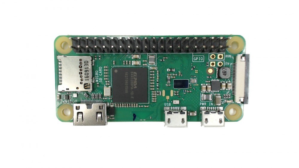
Then we installed the spacers and secured them with four plastic bolts from underneath the Pi.
![]()
Attach Zero HAT
Join the Flick Zero to the top of the Pi by gently pushing the female header onto the Raspberry Pi male header.
Easy stuff, no? At this point if you’ve got your hands on the Flick Zero case, just skip to the next bit to see how to put it all together.
Still with us? You with be using the case to house your Flick Zero then. No worries – it’s not a game changer.
All you have to do now is screw the last four plastic bolts to hold the Flick Zero in place.
And there you are – you’re a Flick Zero hero and your Zero is good to go.
Assembling the Flick Zero case
Got a Flick Zero case? Read on…
The case really is the perfect housing for your Flick Zero. So here’s how to sort it.
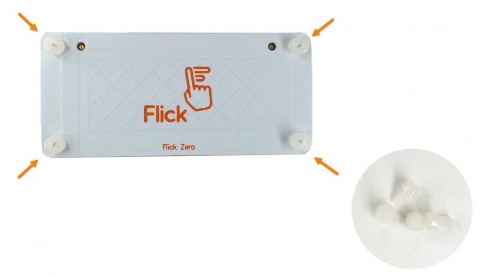
First we removed the protective plastics by pulling ever-so-gently out the two sides of the bottom part of the case to unhook the top.
This let us lift off the top cover and prise the case apart. Inside we found four rubber feet and a couple of suction cups.
Fixing the rubber feet onto the bottom of the case was a sinch. We simply pushed and twisted them through the holes – though we did find a small screwdriver helped to tuck-in the top part of the feet. Gently does it!
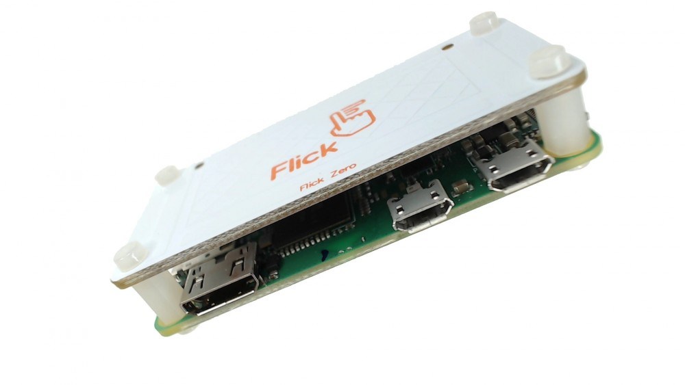
Add your Zero
Next we popped-in our Raspberry Pi and attached the Flick board on the side of the case by the openings for the various connectors.
Make sure the PCBs of the two boards are aligned within the grooves of the panel like this:
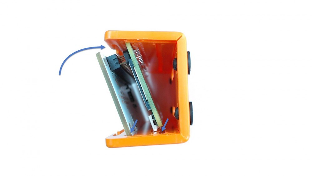
And then we rotated them into position so the Pi and Flick board were nice and snug in the bottom part of the case.
Finishing Up
The suction cups aren’t really essential. So if you simply want to close the case without using them, read the next bit. But if you’re like us and do have a soft spot for the little suckers, then skip down to where we show you how to put things together with the suction cups.
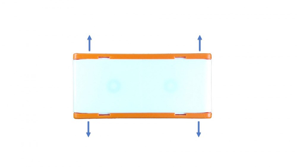
Ready to pop the case together?
Gently flex the sides of the bottom part of the case to create a gap so you can slide the white panels back in.
(Top tip: using a Pi Zero 1.3 or W? Be extra careful when you remove or insert the white panel – the camera connector makes it a really tight fit. You may have to flex the case a tad more.)
And now your Flick Zero is good to go!
Assembling your Flick Zero with it suction cups is almost as easy.
Remove the knock outs for the suction cups and install the cups on the two white panels. (It’s easy, but check the FAQs below if you’re not sure how to do this.)
Gently flex Push the sides of the bottom part of the case to create a gap to slot the white panels back in.
(Top tip: using a Pi Zero 1.3 or W? Be extra careful when you remove or insert the white panel – the camera connector makes it a really tight fit. You may have to flex the case a tad more.)
And your Flick Zero is good to go!
Flick Large
Right, now the final version of Flick – Flick Large Board.
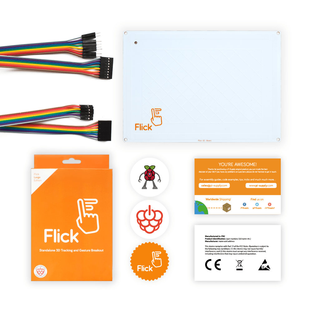
Here’s the kit you should have in your box:
- 1 Flick large
- 1 Jumper cable female to female
- 1 Jumper cable female to male
- 3 Stickers
- 2 Info cards
Wire your Flick Large
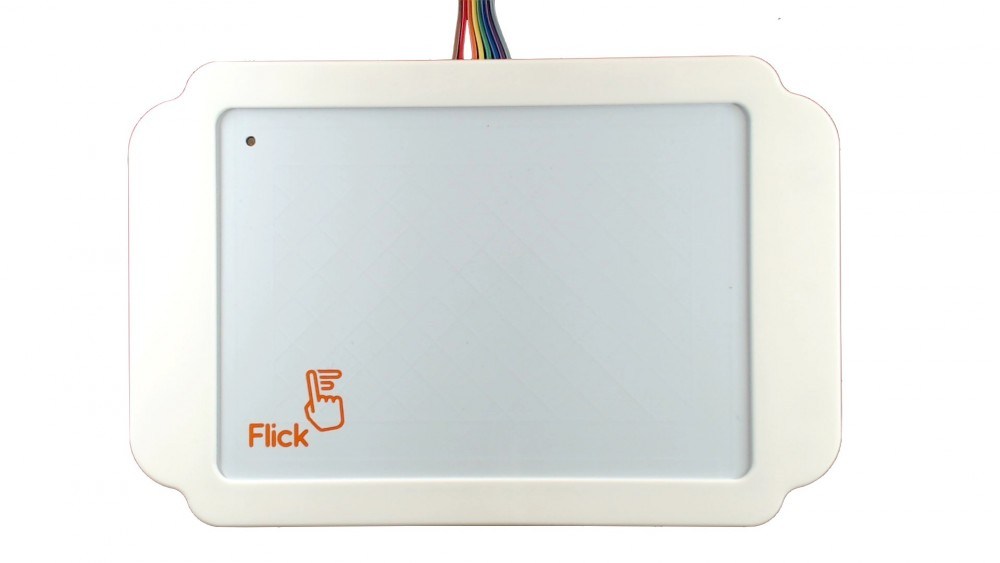
First things first. We took the female to female jumper cable and connected up the Flick large to our Raspberry Pi…
Assembling the Flick Large case
The Flick Large case is just about perfect for housing our Flick Large. That’s because it’s been ingeniously designed so that it can still give access to the connector at the back. OK, maybe ‘ingenious’ is over-egging it a tad, but it’s a nice bit of thoughtful design.
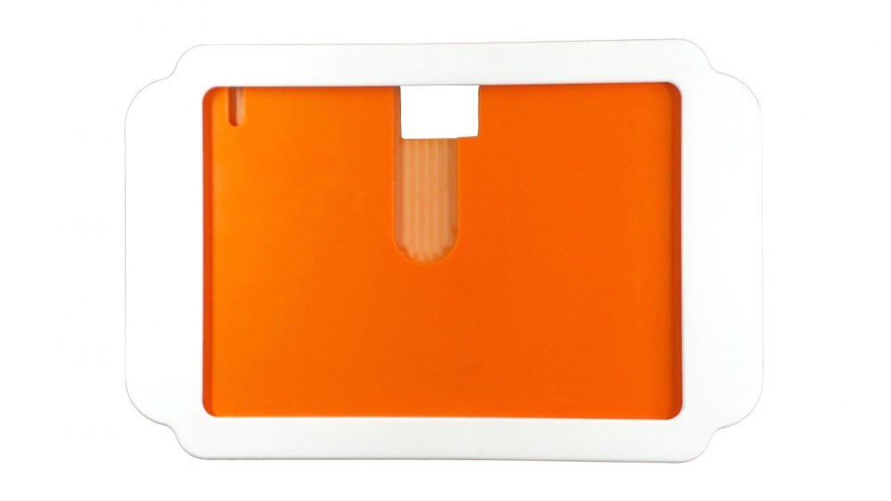
Here we go…we pressed lightly at the back of the case to decouple the back panel…
…then slide the panel out…
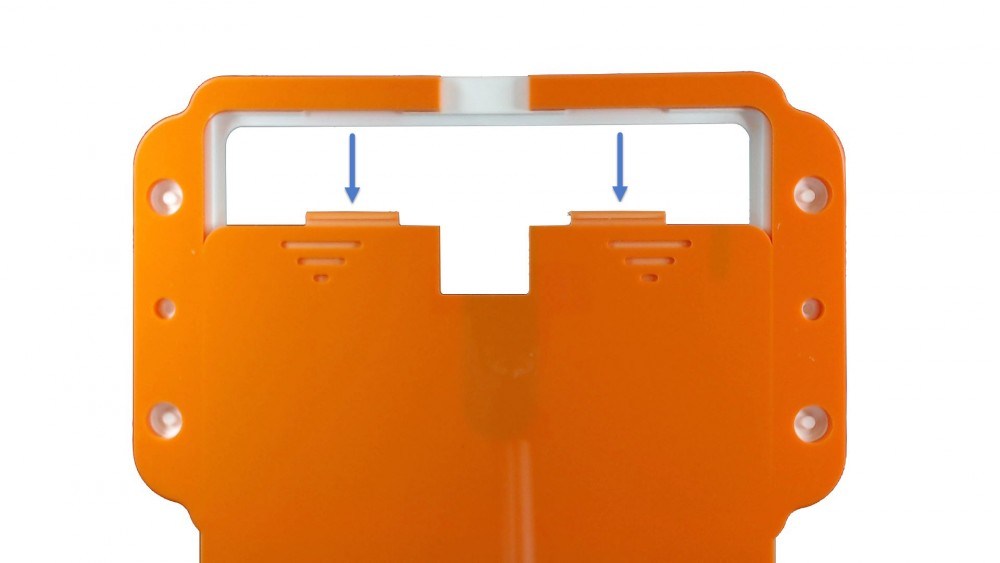
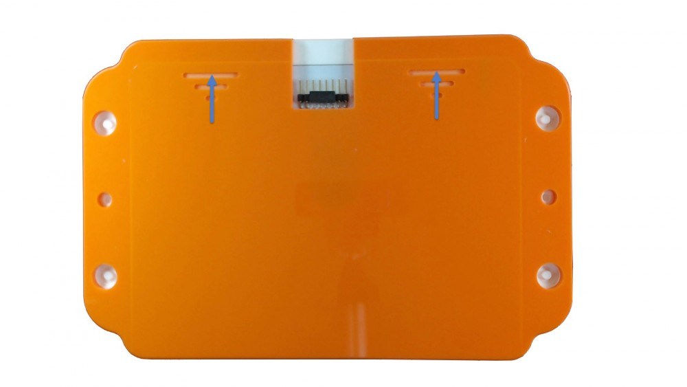
…before slotting-in the Flick Large top corners first.
Then we simply slide the panel back in place until we heard a distinct click.
And bingo – our Flick Large is ready to large it!
Check out these FAQs if you fancy adding suction cups to your Flick Large.
Now it’s time to clear up any burning questions you may have about Quick Flick.
FAQ
Why should I use suction cups anyway?
In a word, hide-ability. Is that a word? Anyhow, the suction cups let you conceal your Flick behind or under any hard flat surface. Not only does it keep your Flick safe from scrutiny, it also makes you feel like James Bond.
To install the suction cups, simply use something long and pointy to pierce through the plastic of the case then push the cups in place with the help of a screw driver.
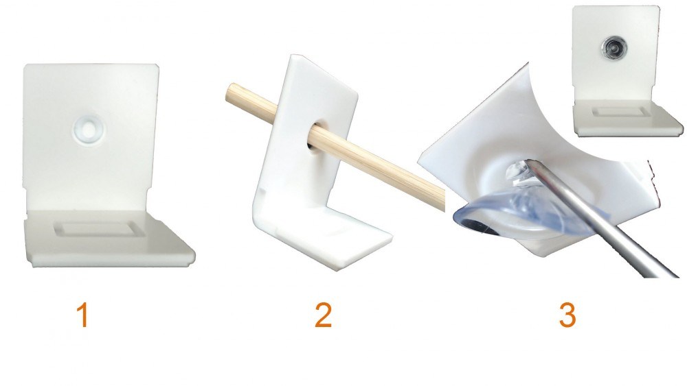
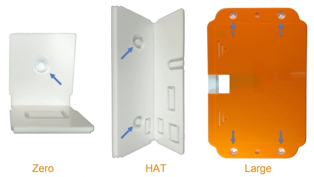
Below you can see where the knock off points for the suction cups are for each case. The Flick Zero case has two (one on each panel), the Flick HAT case has four (two on each panel) and the Flick Large case has four.
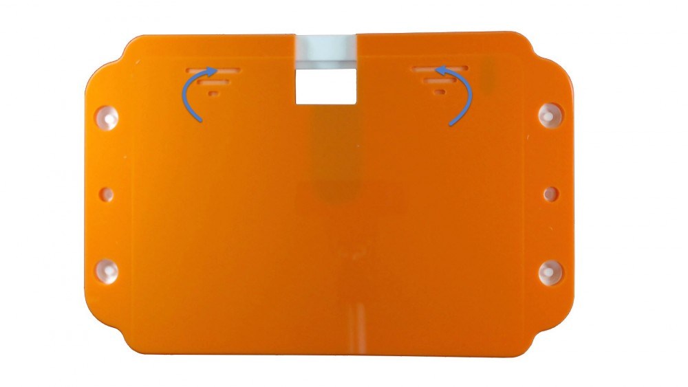
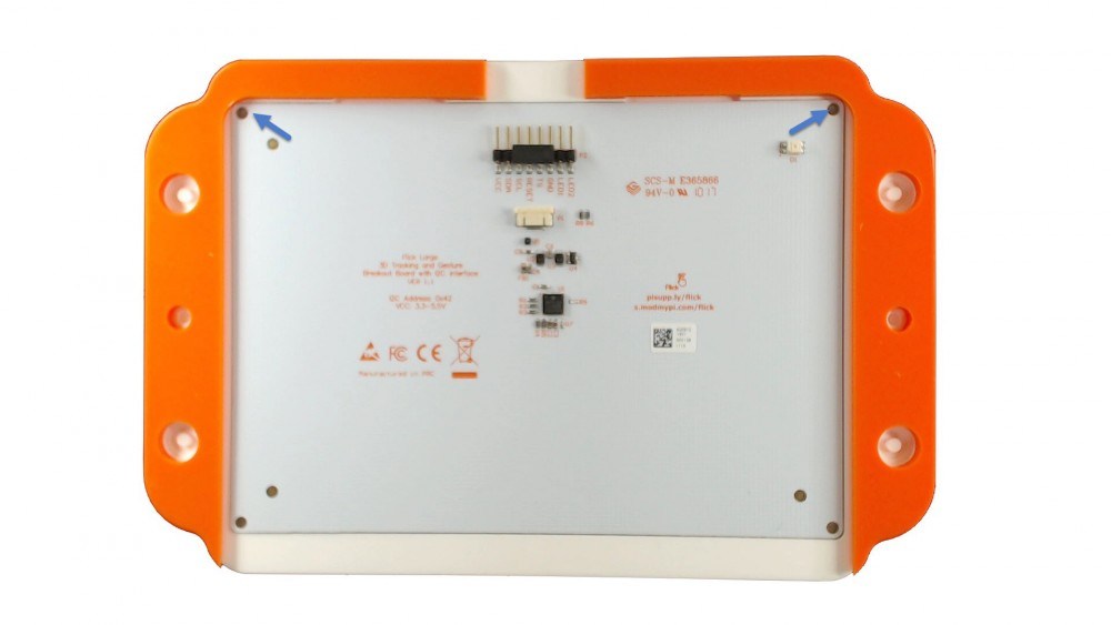
Can I install the Flick Large case with screws?
If you’re really handy with a drill, the Flick Large case lets you use screws to secure it in place. Look for the two drill holes on either side (use a 3mm drill bit).
![]()
Can I use the HAT and Zero case with the Flick Large?
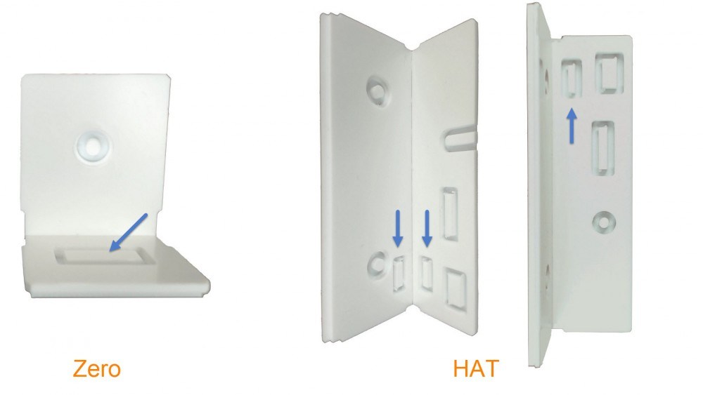
Good news – both the Flick Zero case and the Flick HAT case come with knock outs to allow the Flick Large cable to pass through when the cases are closed. The Zero comes with two knock outs, the HAT comes with three.
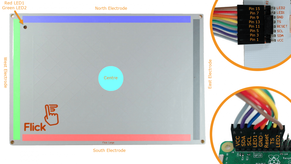
How do I drive the LEDs on the Flick Large?
The Flick Large comes with a customisable dual colour LED. The Red is connected to Pin 7/GPIO 4 of the Raspberry Pi and the green to Pin 15/GPIO 22. You can simply connect them to other pins if you need Pins 7 and 15 for something else.
Why is the XYZ reported erratically?
Moving your finger over the board alters the electric field. The board detects this change and assigns values for the three axis based on the Gestic® Technology. As your finger moves, you may gradually place the rest of your hand on the board too. This confuses the chip as it tries to figure out which part of your hand to follow. For best results, keep your finger as perpendicular as possible to the board.
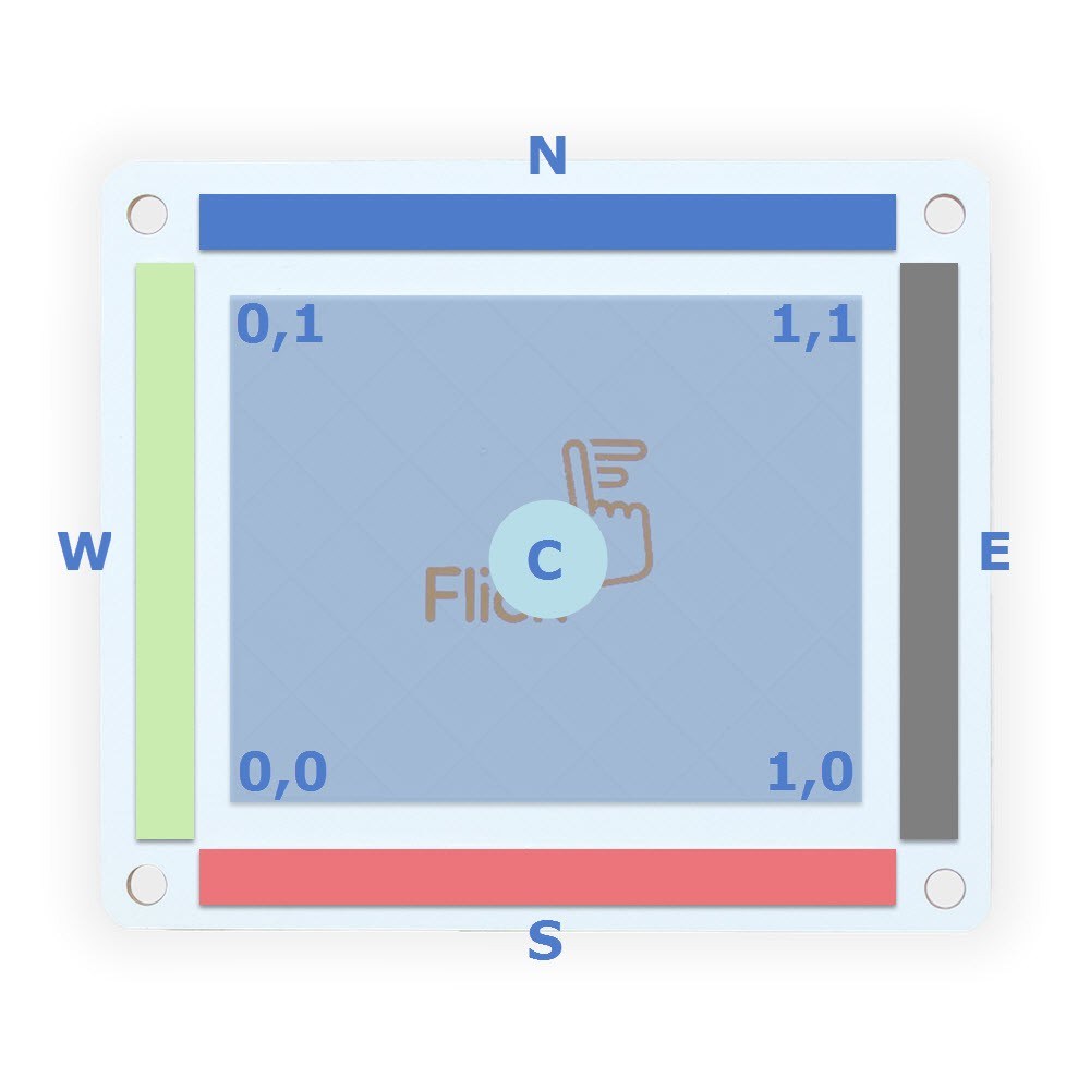
Where are the electrodes and where is the coordinate’s origin?
The Flick board contains five electrodes – one for each cardinal point and one in the middle. As you move your hand over the board these electrodes determine the type of gesture, e.g. moving from the east one to the west one will be read as a Swipe Left.
The set of coordinates used has their origin in the south/west (bottom/left) corner. With the XYZ gesture each set of coordinates spans between 0 and 1 (independently from the type of board used). What is read then is not the physical distance between two points on the board, but rather the percentage of that length. On the picture we showed only two of the coordinates but bare in mind that in reality there’s a third related to the distance of your hand from the board.
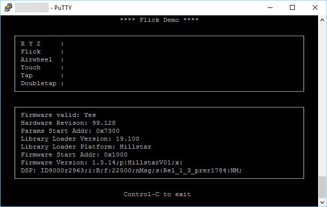
How can I check everything is working?
East. Just run
| flick-demo |
on the command line and you should get a screen like this:
Other software queries? Check out our GitHub repository right now.
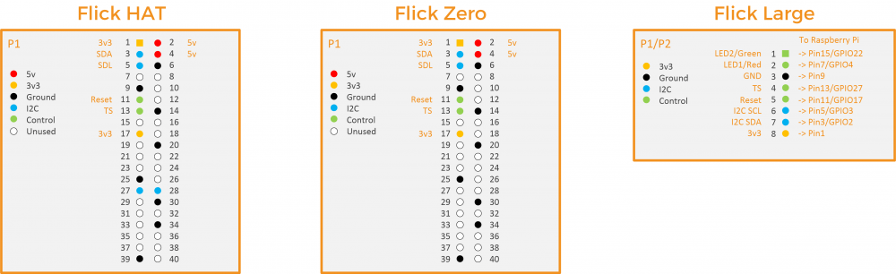
Which pins are used by Flick?
Here’s a plan to show you the pin layouts for each flavour of Flick. (Each pinout is shown from the point of view of the board’s connector. When looking at the Flick Large, note on the left the ‘To Raspberry Pi’ which explains how each pin is mapped on the Raspberry Pi header.)
So there you go, Flick buddies. Now you can operate your Flick with a mere wiggle of your digit. That’s our cue to wave goodbye until next time…
Like what you read? Why not show your appreciation by giving some love.
From a quick tap to smashing that love button and show how much you enjoyed this project.

