It’s amazing what you can do with a few bits and pieces and your trusty Raspberry Pi. We’ve already created any amount of awesome stuff using the Pi as a control centre. So when we sat down to throw some ideas around, it didn’t take long to have a lightbulb moment. Literally.
It revolves around our steampunk ad sign – and how to control the brightness and blink rate of those DC light bulbs. And it all seemed so achievable, you could say we were incandescent with excitement. Now we’re going to take you through how we made it happen.
We’ll use an analogue to digital converter to translate the readings from the potentiometers into something the Raspberry Pi can work with, whilst the Open Collector Drivers which control the bulbs are triggered using PWM on the Raspberry Pi GPIO pins.
Let’s start by breaking things down into seven bitesize steps:
- Connect one bulb to the Pi and switch it on/off using Node-RED and PWM
- Connect the potentiometers to the Pi
- Install the Node-RED analogue to digital converter (MCP3008) node
- Write the Node-RED flow for the potentiometers
- Write the Node-RED flow to control the bulb using the potentiometers
- Write the Node-RED flow to control all the bulbs
- Make a circuit board to combine seven Open Collector Drivers and an analogue to digital converter
All set? Let’s do this thing…
But before we do, you’ll need to know your way around a soldering iron and a knowledge of Node-RED programming. You can find two simple Node-RED projects in the free to download MagPi magazine, ‘Cheerlights Orb’ in MagPi magazine Issue 41, pp58-59 and ‘WakeDino’ in Issue 47, pp 44-45.
Connect a bulb
We used 24V 25W DC incandescent bulbs in our Steampunk Advertising Sign project. As each was wired individually, each can be controlled individually. The Raspberry Pi GPIO pins only provide a signal of 3V3, so they can’t switch the bulbs directly.
But we can use a clever open collector driver (Thingatron). If we want to control each bulb separately – and for the best blink effect that’s a must – we’ll need fourteen of them. As we know to our cost, more complexity = more chances of error creep. So to keep things simple we’ll start with just one bulb (which can be done on a breadboard). Breadboards are fab for prototyping and making sure something works; but for a more robust solution, we’ll be soldering the components on to stripboard or Veroboard – or even a custom-designed PCB.
Before we start, here’s a warning – please use 1k ohm resistors at the base of the Darlington Pairs – check our footnote to find out more.*
Right, here we go…
Connect together a Darlington Pair, diode, resistor, the DC power supply for the bulb and the lampholder (as in Figure 2 below). Connect the resistor to the physical Pin 3 on the Raspberry Pi.
Now connect the Pi to a monitor and keyboard and open Node-RED (Find it under Programming, Node-RED).
Drag a GPIO output node, and set it to Pin 3, Type PWM output. Name it Lamp 1.
Drag an inject node on to the flow, change the payload to a string and type in 100.
Drag another inject node on to the flow, change the payload to a string and type in 50.
Drag another inject node on to the flow, change the payload to a string and type in 0.
Now connect all three inject nodes to the GPIO output node. Click the red “Deploy” button at the top right.
Click on the different inject nodes. Voila! These should turn the lamp on full brightness, on half brightness or off.
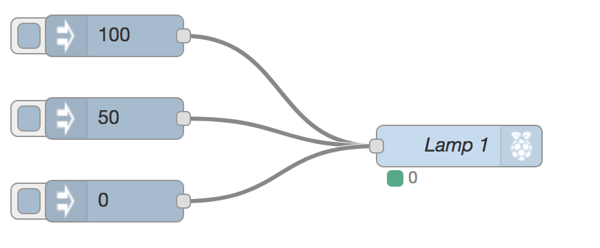
Figure 1
Adding the potentiometers
Firstly, switch off the Pi and the DC power supply.
Now connect the MCP3008 analogue to digital converter and resistors to the circuit (see Figure 2). The datasheet for the MCP3008 gives a diagram of which leg of the chip is which. There’ll be an indentation or ink blob on the chip to mark the end where Pin 1 is.
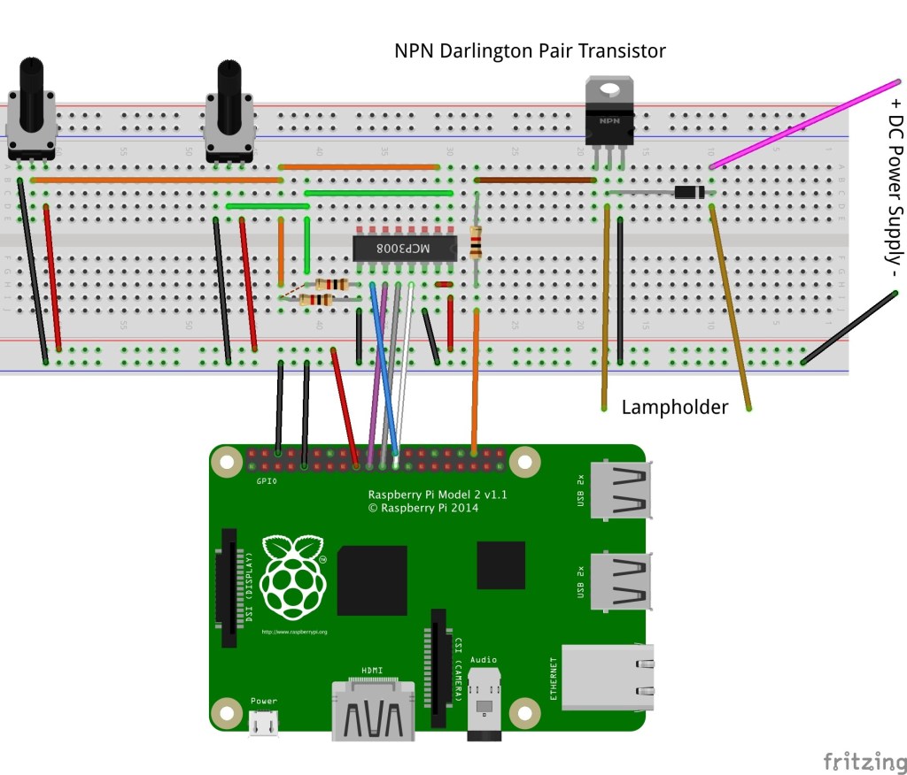
Figure 2
| MCP3008 (Pin) | Wire Colour | GPIO Physical Pin | Other |
| VDD (16) | Red | 1 (3V3) | MCP3008 VRef (15) |
| VRef (15) | Red | 1 (3V3) | n/a |
| AGND (14) | Black | 6 (GND) | n/a |
| CLK (13) | White | 23 | n/a |
| DOut (12) | Grey | 21 | n/a |
| Din (11) | Purple | 19 | n/a |
| CS/SHDN (10) | Blue | 24 | n/a |
| DGND (9) | Black | 4 (GND) | Resistor |
| CH0 (1) | Green | n/a | Potentiometer1 and Resistor |
| CH1 (2) | Orange | n/a | Potentiometer2 and Resistor |
The potentiometer is wired:
1 to ground
2 to the Channel required on the MCP3008
3 to 3V3
Install Node Red
We need a special Node-RED node to be able to read from the Analogue to Digital converter. Luckily, one’s already made (hurrah!) – but it’s not in the default palette (doh!). Fear not, because it’s easy ti install the node-red-node-pi-mcp3008 node using the ‘manage palette’ option in Node-RED:-
- Power the Pi back on, but leave the DC supply switched off
- Check the prerequisites on the website: https://flows.nodered.org/node/node-red-dashboard. As at September 2017, this means we need to enable the SPI on the Raspberry Pi using raspi-config from the command line as follows:
Run “sudo raspi-config”
Select 5 – Interfacing Options
Select P4 – SPI
Select yes to enable SPI
Select OK to confi
Select the Finish button
Then open Node-RED and click:
Menu
Manage Palette
“Install” tab.
In the box next to the magnifying glass, search for ‘node-red-node-pi-mcp3008’. Click the ‘install’ button to the right of the ‘node-red-node-pi-mcp3008’ selection. Then simply follow the on-screen instructions.
The node will now appear in the node menu palette in the ‘Raspberry Pi’ section as ‘A/D Converter.
Setting up Node Red for the potentiometers
Drag an inject node and an A/D converter node into your flow and connect them together. Then connect a debug node to the output side of the A/D converter node.
Double click the inject node, change the payload to type ‘string’ and put a 0 in the payload box. This tells the A/D converter node to look at Channel 0 on the MCP8003 chip.
Change the ‘Repeat’ from ‘none’ to ‘interval’ and change the interval to ‘every 5 seconds’ to get a reading from the potentiometer every five seconds.
Now tick the “inject once at start” button and click “Done”.
Double click the A/D converter node and change the Input pin to “A0”. The Device ID should be CE0. Click “Done”.
Click the “Debug” tab on the right-hand side (under the Deploy button).
Click deploy – a number should appear every five seconds. This will be a number between 0 and 1023, depending on how far the potentiometer is twisted.
Repeat all the steps above, only this time change the Channel to 1. You should now be able to see the output of both potentiometers.
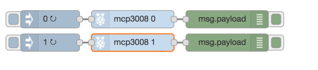
Figure 3
Next, we’re going to write the Node-RED flow to control the bulb with the potentiometers.
Thanks to the potentiometers, controlling the length of time the bulb is on or off is child’s play. Controlling the brightness is a piece of cake, too. But what’s more of an ask is to get the time delay AND brightness to effect the same bulb simultaneously – you need a function node to store the values for this neat trick (this part is based on work by Andy Stanford-Clark – with thanks!).
To make life easy, we’ve put the flow on Github as Step E Flow.rtf which you can import into your own Node-RED. (Copy the text document to the clipboard, then in Node-RED click Menu, import, clipboard and paste it in.)
OK, almost there. Now we’re going to write the Node-RED flow to control all the bulbs.
Happily, you can sort this before all the bulbs are connected!
We doubled up the bulbs for each input – so two bulbs are triggered on one GPIO input. This makes the Node-RED flow simpler.
Using the flow used in Step E as the basis, you’ll find our final flow in Github AdvertisingSignTotalFlow.rtf, which you’re again free to paste into your Node-RED and adapt however you like (we’re generous like that). So knock yourself out and have fun with the sequences – you could even write a function node with an array to do this.
Whatever you do, don’t have another tab with the same GPIO pin as this can give weird results.
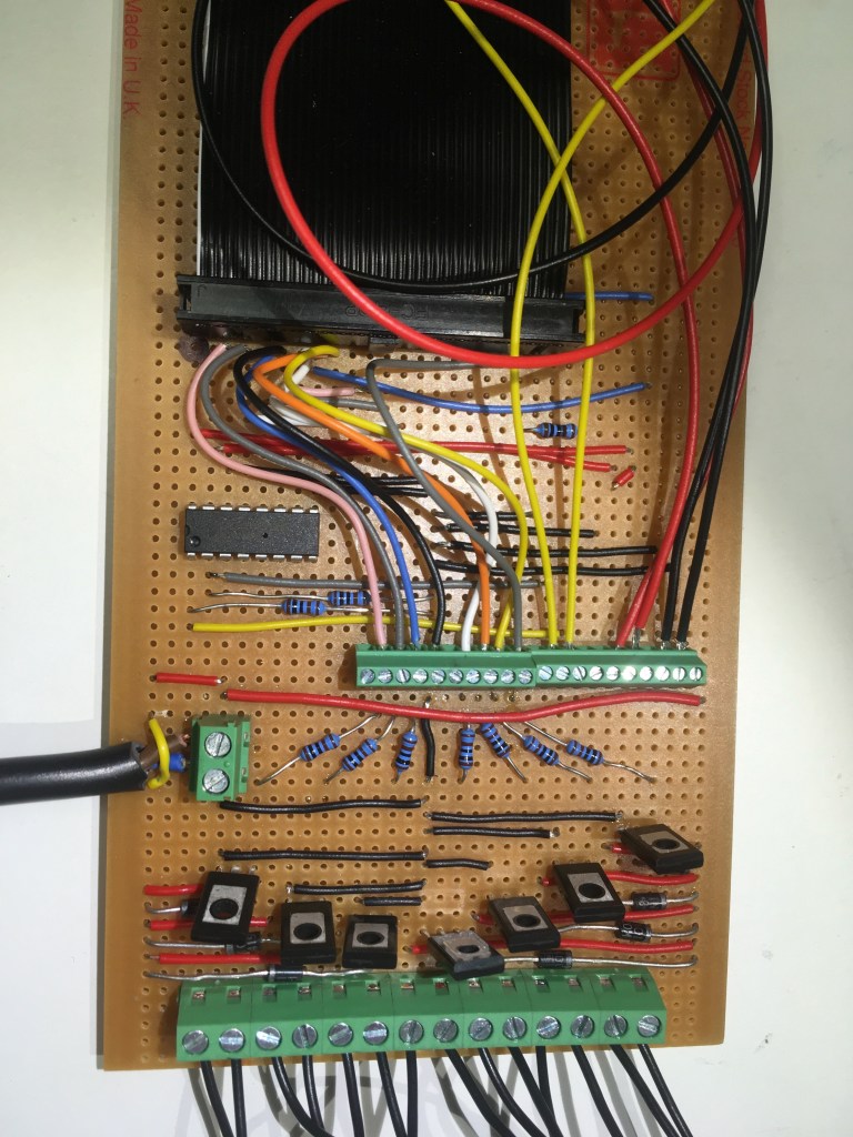
Make your circuit board
Up until now, you may have done everything on a breadboard and used only one lamp (the flows used GPIO pins that weren’t yet connected to Open Collector Drivers).
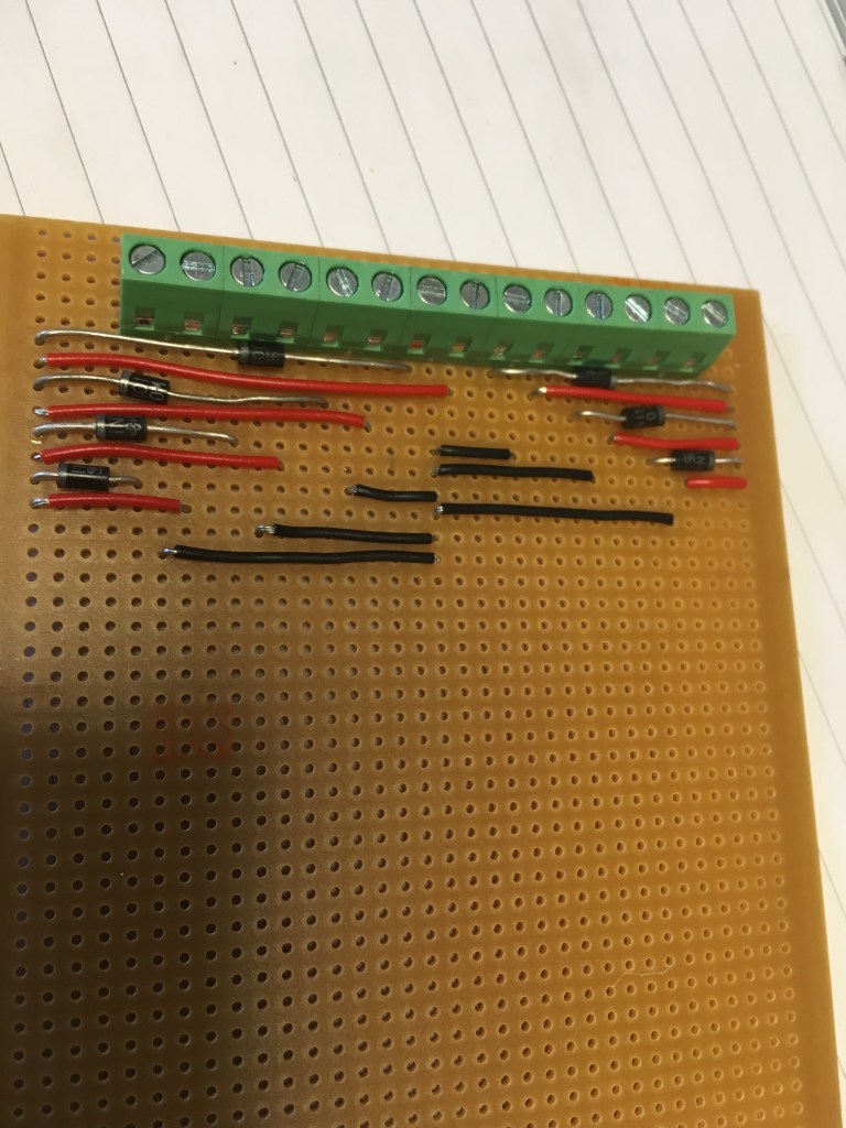
To make everything more robust, we’re going to have to dig out the soldering iron and solder everything together on a single sided stripboard, Veroboard or similar thing. Feel free to create your own design here – but here’s a few shots of our efforts. We used screw terminals where possible and a ribbon cable to make it easy to connect the Pi.
| GPIO Physical Pins | Item |
| 35 | Lamp 1 |
| 15 | Lamp 2 |
| 13 | Lamp 3 |
| 11 | Lamp 4 |
| 7 | Lamp 5 |
| 5 | Lamp 6 |
| 3 | Lamp 7 |
| 24 | MCP3008 Pin 10 |
| 19 | MCP3008 Pin 11 |
| 21 | MCP3008 Pin 12 |
| 23 | MCP3008 Pin 13 |
| GND | MCP3008 15 |
| 3V3 | MCP3008 15 and 16 |

So what do we wish we’d known before we made the circuit?
Well, for one we wish we’d used a teeny weeny tip on the old soldering iron.
For two, we’d recommend triple checking BEFORE you break any tracks on the stripboard (!).
And for three, we’d check for shorts using a continuity tester (on a multimeter) BEFORE connecting a Pi (yup, we fried a couple – doh!).
Oh, and here’s a top tip: you MUST use Darlington Pairs. Using “normal” transistors is a bad idea as you can see…
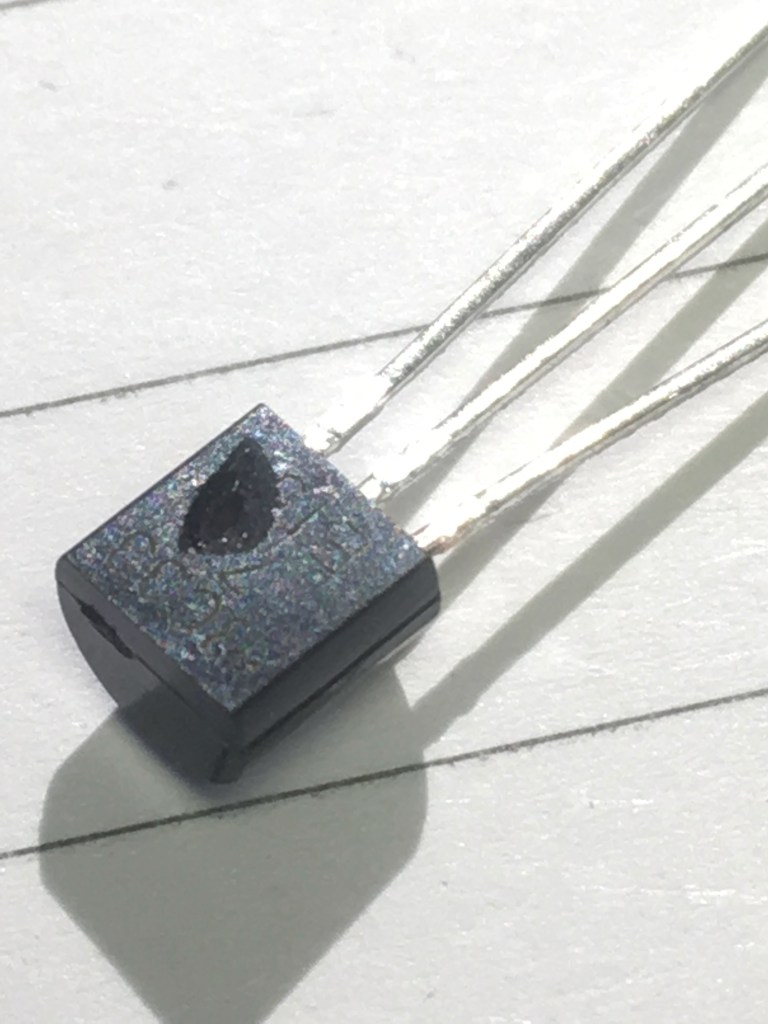
In a transistor, the current of the Load is limited (in the case of NPN Transistor – BC337 to a maximum of 800mA). So if the current it draws is too high, it’ll fry the transistor. Or make it explode. However, your Darlington pair uses two transistors that act as a single transistor – only with a much higher current gain – so you shouldn’t have a problem with the current limit.
Footnote
Remember we mentioned a footnote? Well here we are. The powers that be recommend the Raspberry Pi GPIO pins are used with a maximum of 16mA per pin – and a total of 100mA (0.1A) for ALL the pins. The Thingatrons use 330R resistors to the base of the Darlington Pair. Using 14 of these would give a total of 0.14A.
V/R = I
3.3/330 =0.01A
14*0.01 = 0.14A
By increasing the resistor size to 1000 ohms, we can reduce this to 0.0462A
V/R = I
3.3/1000 = 0.0033A
14* 0.0033 =0.0462A
So there you have it – a (relatively) simple way to control your incandescent bulbs with your Raspberry Pi. We found this project a lot of fun – and very rewarding. Which is glowing testimony to the powers of Pi when used as a control centre.
Like what you read? Why not show your appreciation by giving some love.
From a quick tap to smashing that love button and show how much you enjoyed this project.

