We love our trusty little Raspberry Pi. After all, it’s so incredibly versatile and easy to use. But we know some folk are still getting to grips with it. So we thought we’d show you how to perform a few of the more useful tricks with your Pi.
Ready? Take a deep breath, stretch your fingers, flex your pecs…and let’s begin.
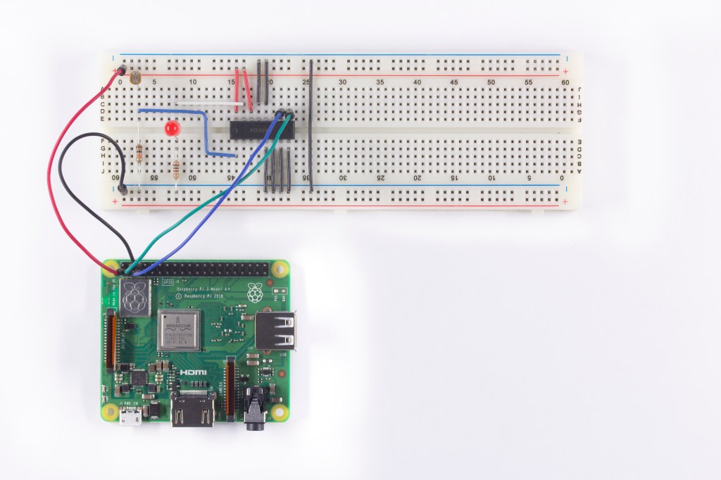
We’ll be looking at how to program your Pi to “measure” the state of one of its GPIO pins as a digital input. We’ll also be learning how you can use the Pi along with an Analogue to Digital Converter (ADC) to measure an analogue voltage. And for good measure, we’ll also show you how the Raspberry Pi can be used with a Digital to Analogue Converter (DAC) to generate an analogue signal.
The steps
We’ll be splitting the exercise into three steps of increasing complexity.
Step 1
To get the ball rolling, we’ll introduce you to the IDLE integrated development environment and to the Python programming language. You’ll be tasked entering commands at the Python prompt. And you’ll learn how a single digital input represents a single “bit” of data. Pretty straightforward stuff.
Step 2
Next we’ll introduce you to the concept of creating a file containing a series of Python commands, saving this file as a “computer program” and “running” the program. You’ll see the difference between a digital and an analogue signal and learn how an Analogue to Digital Converter (ADC) can enable analogue signals to be measured. We’ll also present the concept of serial and parallel data interfaces – and how your Pi is configured to use the I2C protocol.
Plus you’ll get to use the “apt-get” command to download and install software packages from the Debian repository. And you can look forward to discovering all about basic data transfer between the Pi and peripheral hardware by reading data from the ADC chip. Finally for this step (it’s a big one) we’ll cover Python’s “while” loop.
Step 3
In this last step we’ll explain how Digital to Analogue Converter (DAC) works and how you can generate an analogue signal with a DAC. We’ll go into a little more detail about the difference between an analogue and a digital signal, and then we’ll see how data is transferred between your Pi and peripheral hardware by sending data to the DAC. As it happens, this nicely leads on to using hexadecimal notation to represent binary data.
Lastly, we’ll spend some time checking out the “for” loop in Python, discovering how to reuse and adapt code by loading and editing it from the earlier step.
We created all these exercises using a Raspberry Pi Model B with a 26 Way GPIO Pin header. Of course newer models have a 40 Way GPIO header, but the first 26 pins are the same.
Now check out these files for the exercises and for our Raspberry Pi Setup guides
- Bill of Materials for exercises
- Analogue IO Exercises – Student Workbook
- Analogue IO Exercises – Teachers Notes
- Raspberry Pi Set Up Guide – Students
- Raspberry Pi Set Up Guide – Teachers
Like what you read? Why not show your appreciation by giving some love.
From a quick tap to smashing that love button and show how much you enjoyed this project.
