Let’s face it, a wireless sensor system is not only pretty damn cool, it’s also pretty handy too. And that’s especially true if that system can work over long distances. So we thought we’d do you guys a favour by showing you how to build an easy long-range wireless sensor system with a nifty modular electronics platform called XinaBox.
The XinaBox modular electronics system features stuff like embedded processors, host interfaces, sensors, power, communication and output. And thanks to a standard form factor and compact ‘xBUS’ bus connectors, you don’t need any wires, soldering or breadboards to make interconnections. Simple!
So let’s take a look at how XinaBox can be used to prototype a wireless sensor system capable of working over remarkably long distances and even in the most challenging of environments.
First of all, let’s clarify exactly what situation we’ll be setting up our system for.
In this case, let’s assume we’re creating wireless monitoring for safety applications. This is perfect since our XinaBox system can be used across a large sprawling site spanning with plenty of obstacles. Think manufacturing plants or container ports.
Better still, both Bluetooth and WiFi systems would be a no-no in these scenarios as they each have a pretty short range.
Agreed? Let’s go…
The Basics
We’re going to use LoRa as our modulation for digital wireless comms. This low-cost off-the-shelf device can reach up to 15km while using a mere smidgeon of power.
Just make sure you’re operating in unlicensed bands, though.
Of course, there’s no such thing as a free lunch – and the trade-off for long range is that it’s narrowband and only really good for sending small amounts of data. “Whoa – that’s perfect for wireless sensors!” we hear you scream. And we wouldn’t disagree. But for the record it’s no good for transferring files, surfing the web and streaming video. Which in this case is fine.
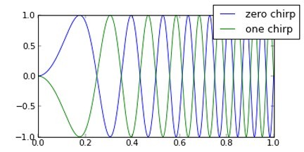
With this little beauty we can whizz comms over many kilometres with only a few milliwatts of power. That may seem like magic, but it’s all made possible by the chirp spread spectrum modulation and what’s known as ‘coding gains’ which increase receiver sensitivity so you can pick up signals from beneath the noise floor.
In plain English, LoRa lets you spend more time on-air and transmitting to transfer a certain size payload than you would with a more traditional modulation type (e.g. FSK or ASK/OOK). Having said that, this ain’t gonna prove problematic for small payloads.
For a more about LoRa modulation and comparison to other types, check out Part 3 of Bill Marshall’s post series, RF Communication and the Internet of Things.
Before we go any further, many folk seem confused by the relationship between LoRa and LoRaWAN. It’s really not rocket science. Whilst LoRa simply provides a channel for information, LoRaWAN builds on this to enable massively scalable networks with addressing and a comprehensive standard that covers device provisioning, different classes of service and interoperability etc.
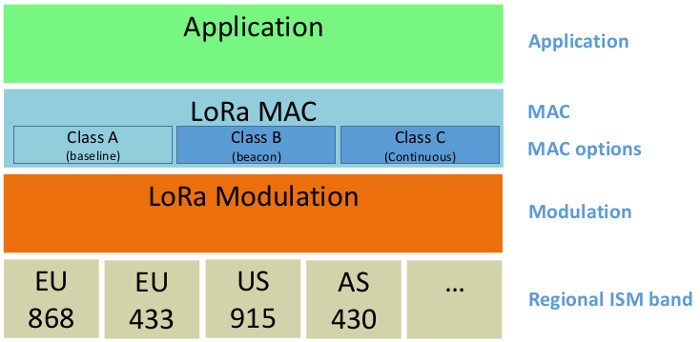
Don’t panic – we’ll be using a far simpler system than this LoRaWAN MAC layer.
Here’s a point to note. LoRaWAN is fantastic for rolling-out a national or international network. But it does make life more complex with the need for servers and additional constraints. With our safety application, the requirements are quite simple. And, because we want to eliminate as much complexity as possible and remove any reliance on external services, we’ll be using a very simple peer-to-peer system — and not LoRaWAN.
For more on LoRaWAN, try A Closer Look at LoRaWAN and The Things Network.
Choosing Hardware
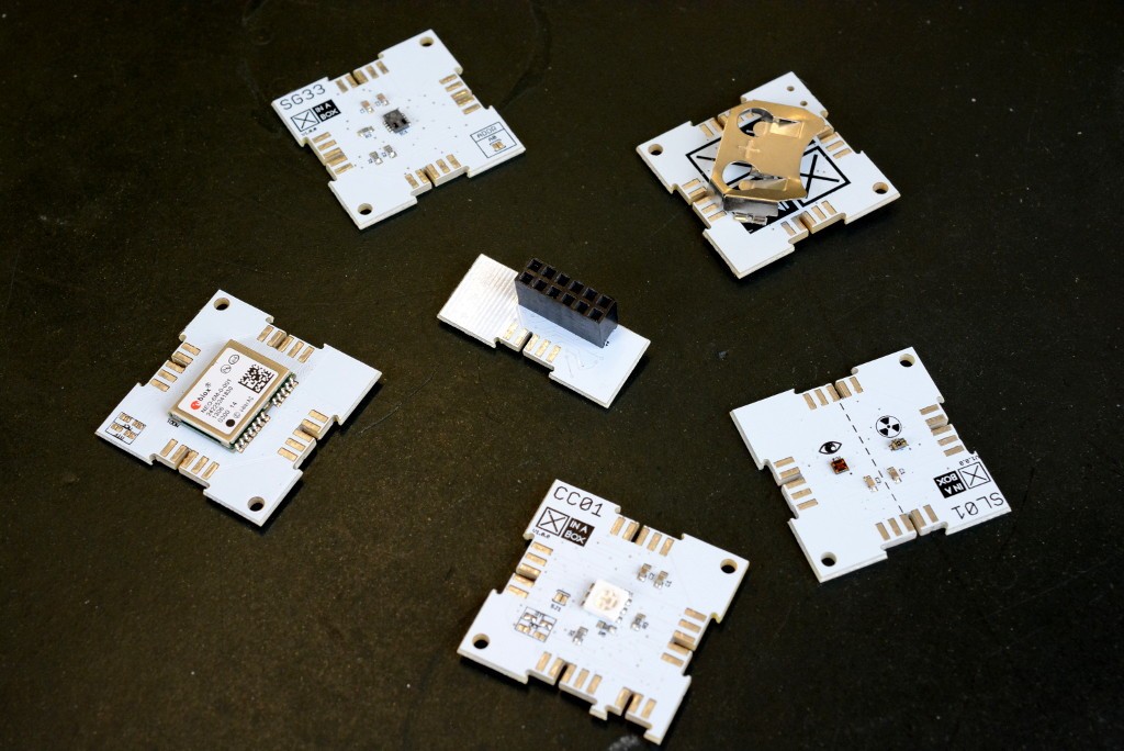
When it comes to hardware to use with XinaBox, you can take your pick. Here are just a few of the many xChips out there which provide an ATmega328P microcontroller core (174-3696), Raspberry Pi interface (174-3694), GPS (174-3740), VOC/eCO2 gas (174-3732) and visible/UV light (174-3738) sensors, and power supply via a CR2032 coin cell battery (174-3721).
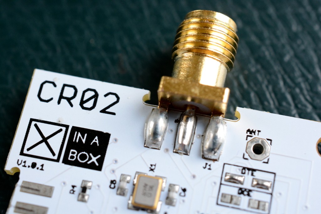
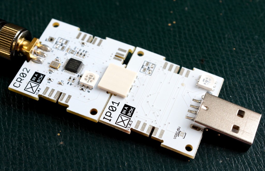
The CR02 (174-3699) is an xChip module based around an ATmega328P microcontroller, paired with an RFM95W LoRa radio configured for 868MHz. Other variants include CR01 (174-3698) and CR03 (174-3700), which are configured for 433MHz and 915MHz respectively.
Of course you’ll make sure you use the correct module (and thus band) given your location — e.g. 433 or 868MHz in Europe and 915MHz in the US.
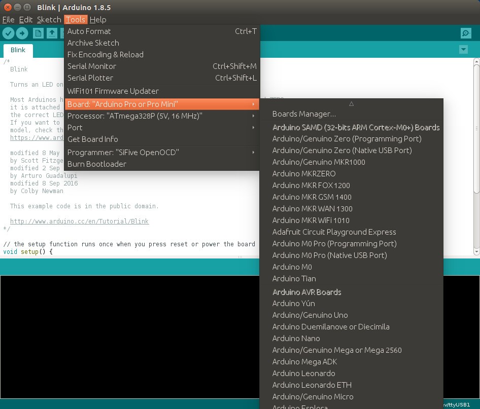
These boards are compatible with the Arduino Pro and Arduino Pro Mini, hence are supported by the Arduino IDE without the need to install any additional board support packages. But bear in mind the CPU/core boards do not integrate a USB interface, since this might only be needed for programming and would add to the physical size and cost. So we’ll be using the IP01 (174-3703) programming interface, which is built on the FT232R and in Linux enumerates as /dev/ttyUSBn.
Still with us? Cool. Stay tuned for our next post where we’ll move on to programming a CRO2 module (or ‘xChip’) which features an integrated microcontroller and radio — and then sending and receiving data across a LoRa wireless link. How exciting is that?
Like what you read? Why not show your appreciation by giving some love.
From a quick tap to smashing that love button and show how much you enjoyed this project.
