This project shows you how to convert a SNES gamepad to USB controller. The gamepad will be recognised as a keyboard by your computer. Each button will output a different letter. You can then map this to the controls of any game. There are many variants of the SNES gamepad so the images here might not exactly match your controller physically. You should be able to use these instructions as a guide for any SNES gamepad.
1. Disassemble the controller
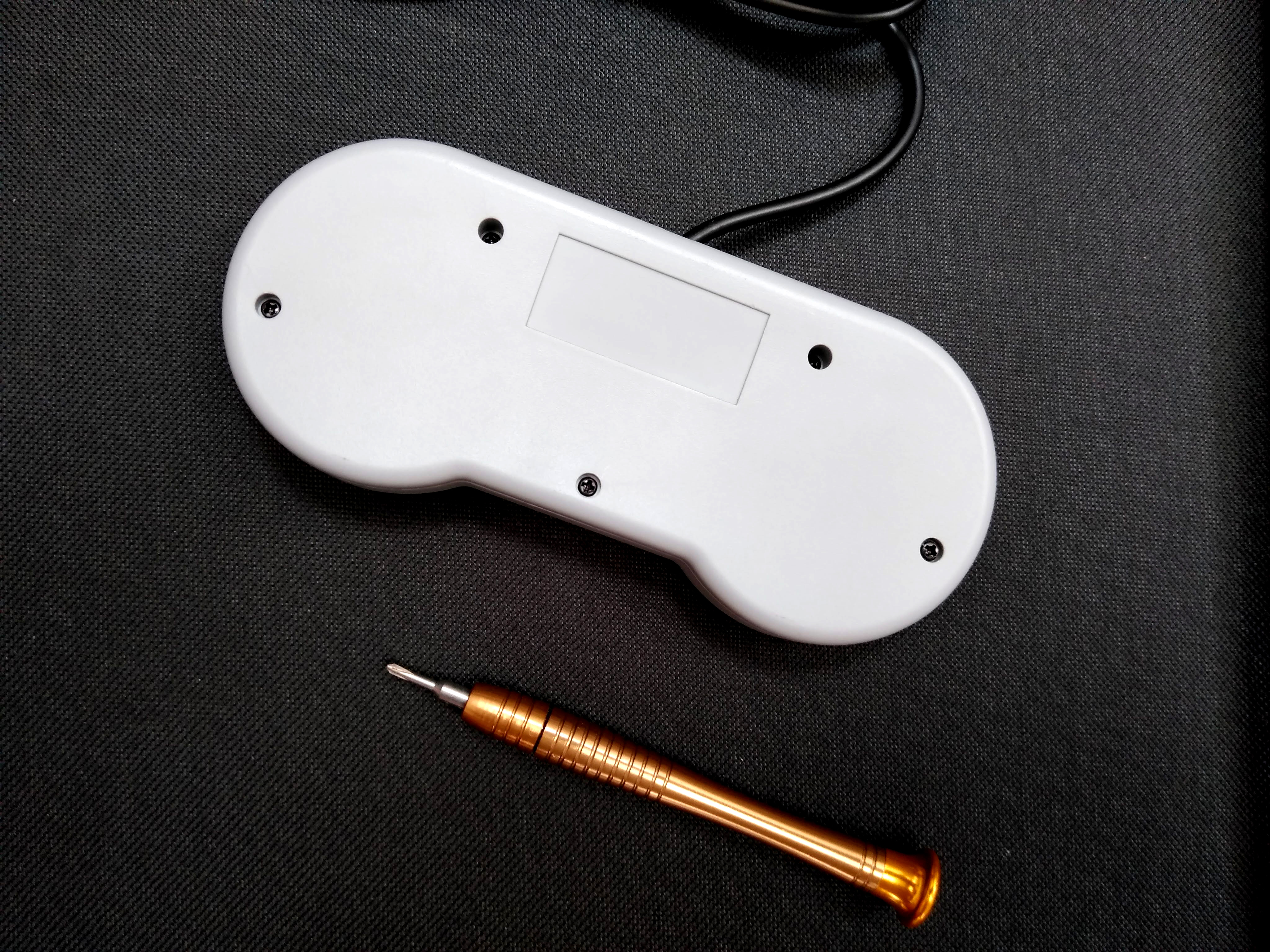
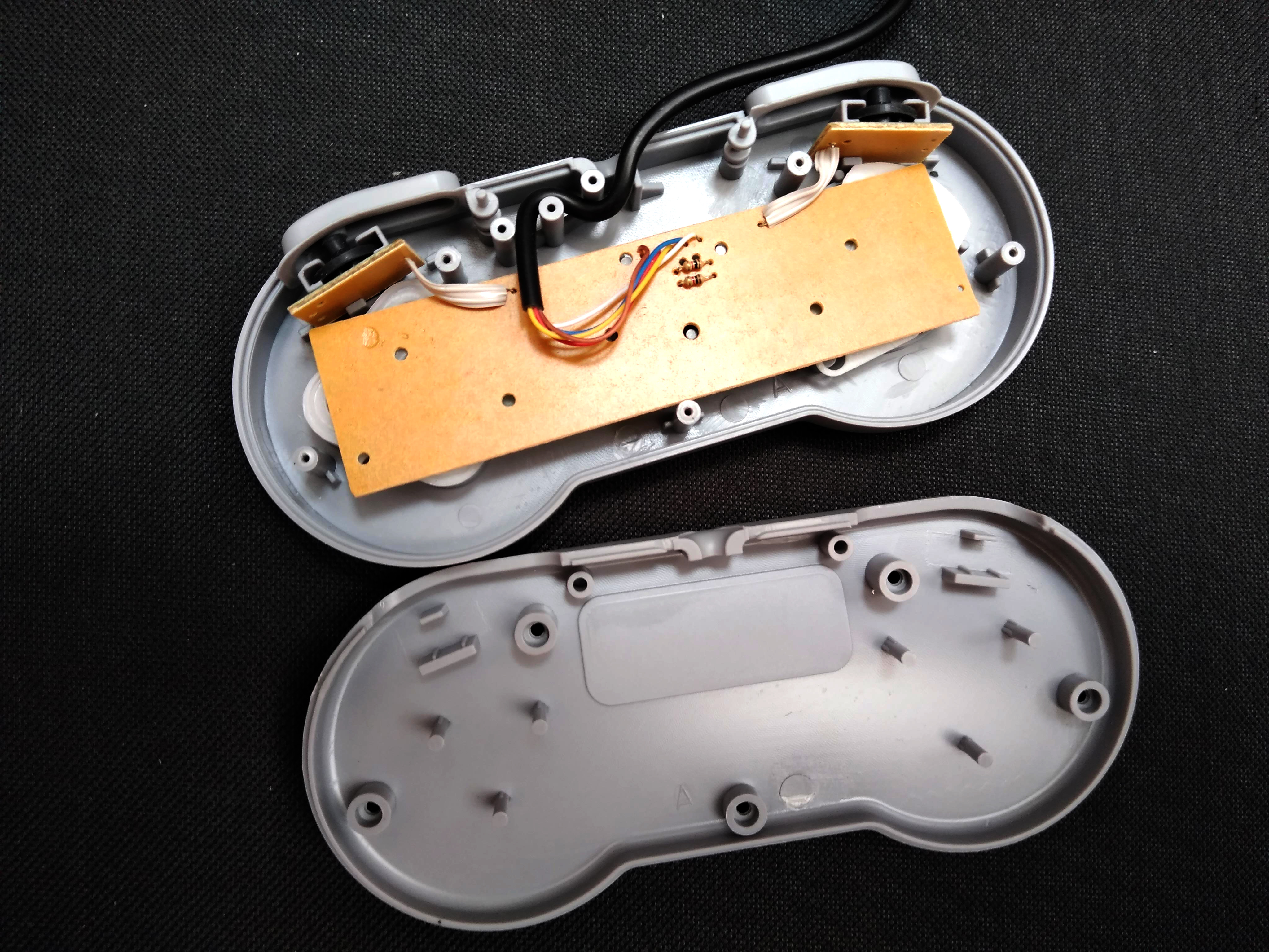
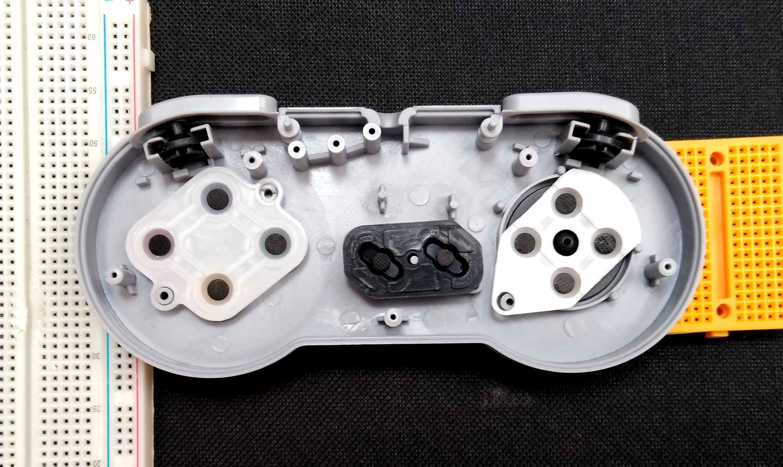
- Take off the screws that hold the case together.
- Carefully take out the PCB, noting how all the buttons parts are fitted.
2. Solder the cables
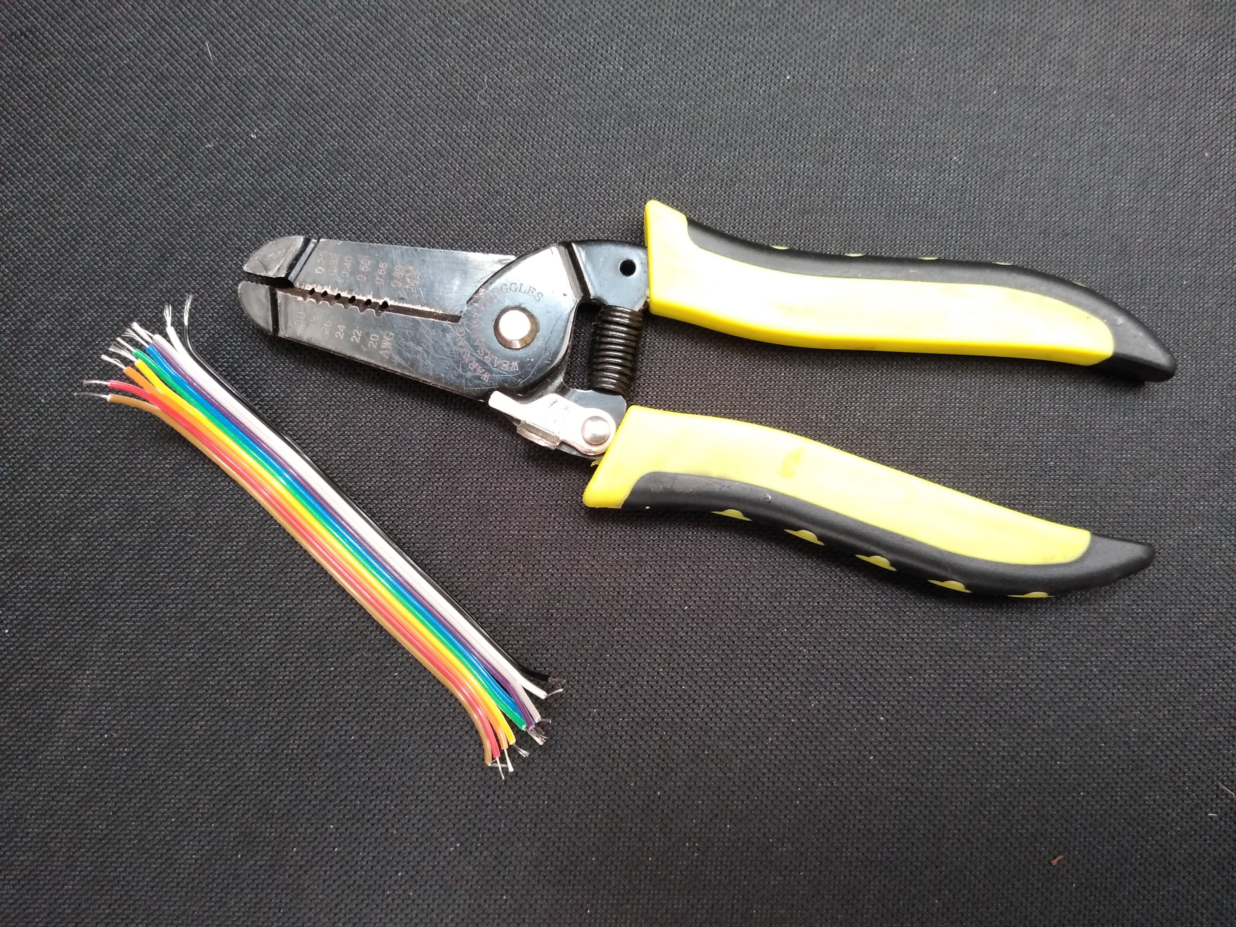
- Cut around 12cm of ribbon cable, split the ends and strip them. You can always trim the cables if they’re too long so ensure they are long enough.
- Using a Stanley knife, scratch some of the green on the ground connection of the PCB to reveal the copper underneath. You can spot the ground contact because it is the connection common to all the buttons.
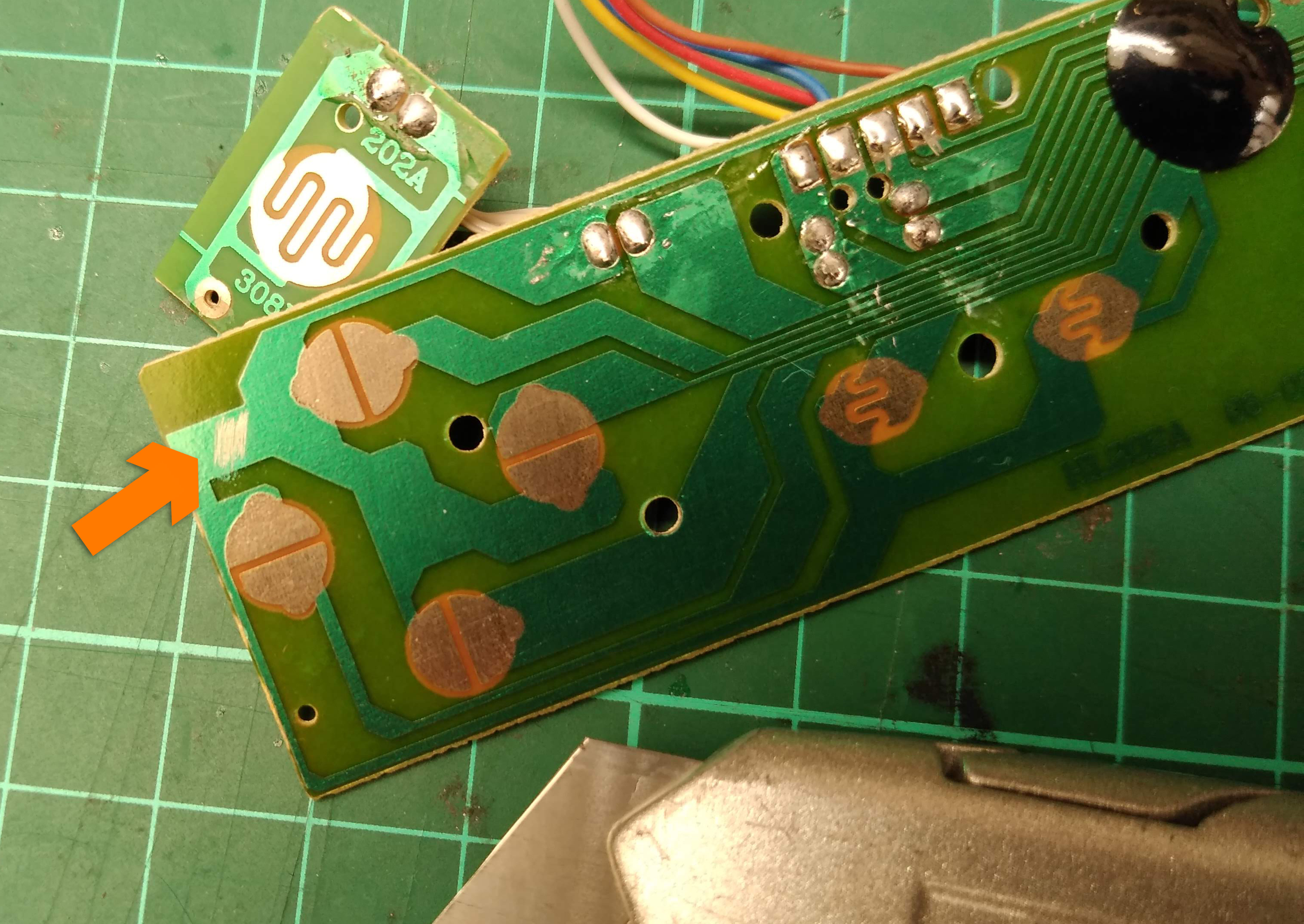
- Solder the black cable to the ground contact that you just scratched.
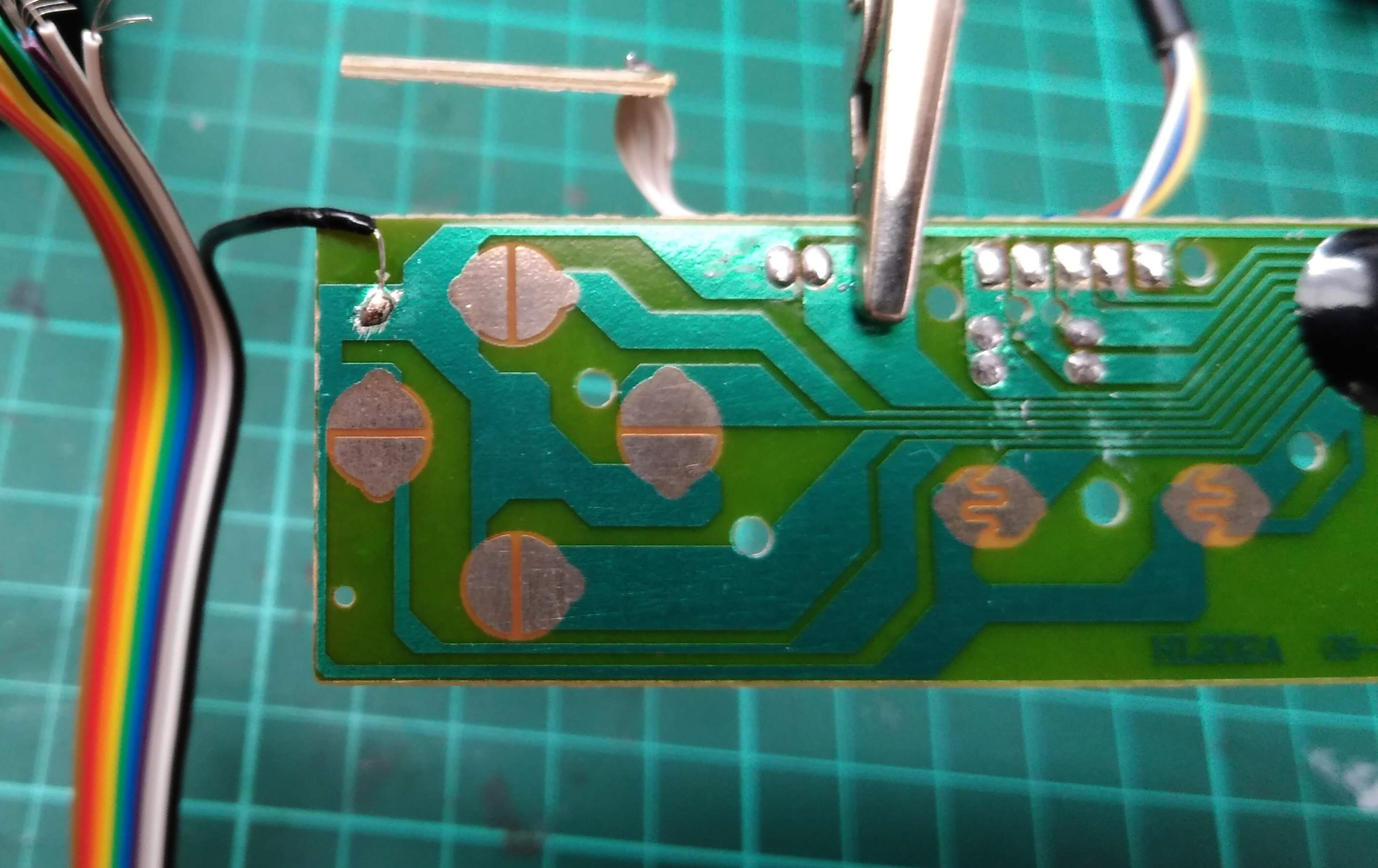
Using the same technique as above, solder the following wires to the buttons. Ensure that you solder to the live connector on each button, not the one connected to ground.
- White wire to Up button.
- Grey wire to Right button.
- Blue wire to Left button.
- Orange wire to L1 button.
- Yellow wire to Start button.
- Green wire to Select button.
- Tear the red and brown wires off.
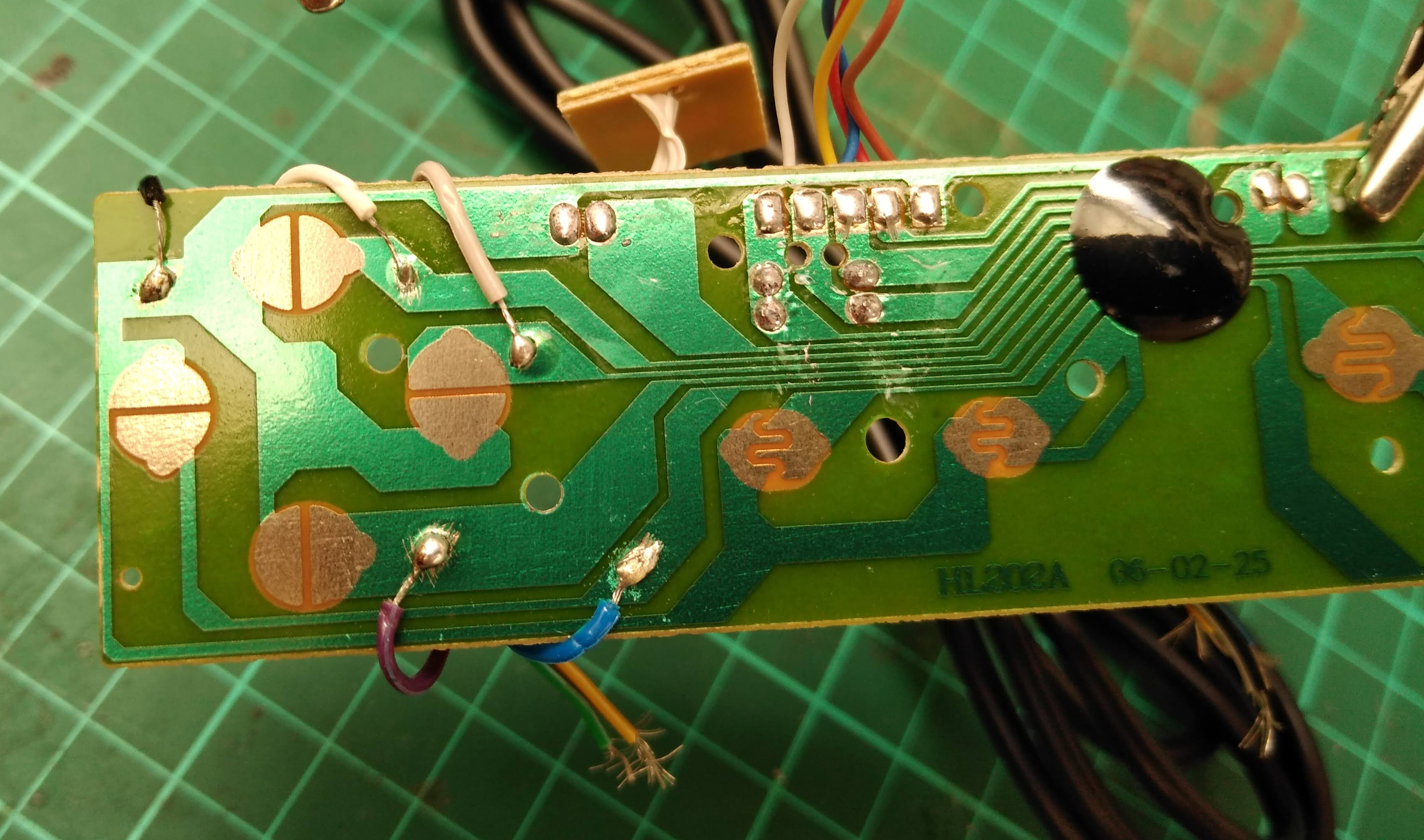
- Cut another piece of ribbon wire keeping only the white, grey, purple, blue and green wires.
Using the same process as before, solder the following:
- White wire to button B.
- Grey wire to button A.
- Purple wire to button X.
- Blue wire to button Y.
- Green wire to button R1.
- Disconnect the original connector cable. You can do this by cutting it or pulling each wire off after heating it with a soldering iron.
Now we’ll solder all the wires to the Teensy, starting with the first ribbon, to do this you’ll need a vise or helping hands to hold the Teensy while you do the soldering.
- Black wire to the ground pin.
- White wire to B0.
- Grey wire to B1.
- Purple wire to B2.
- Blue wire to B3.
- Green wire to B7.
- Yellow wire to D0.
- Orange wire to D1.
Next we’ll solder the other ribbon cable.
- White to D2.
- Grey to D3.
- Purple to C6.
- Blue to C7.
- Green to D5.
3. Programme the Teensy
To programme the Teensy you’ll need Arduino IDE and Teensyduino installed on your computer.
Upload the following code.
#define REPEATRATE 100  // milliseconds

const int pinBtnUp = 0;
const int pinBtnRight = 1;
const int pinBtnDown = 2;
const int pinBtnLeft = 3;

const int pinBtnSelect = 4;
const int pinBtnStart = 5;

const int pinBtnB = 7;
const int pinBtnA = 8;
const int pinBtnY = 10;
const int pinBtnX = 9;

const int pinBtnTrigLeft = 6;
const int pinBtnTrigRight = 23;

const int pinLEDOutput = 11;

//Variables for the states of the SNES buttons
byte buttons[] = {  pinBtnUp, pinBtnRight, pinBtnDown, pinBtnLeft, pinBtnSelect, pinBtnStart,
                    pinBtnB, pinBtnA, pinBtnY, pinBtnX, pinBtnTrigLeft, pinBtnTrigRight
                 };
unsigned int keys[] = {KEY_U, KEY_R, KEY_D, KEY_L, KEY_ENTER, KEY_TAB, KEY_B, KEY_A, KEY_Y, KEY_X, KEY_P, KEY_Q};

#define NUMBUTTONS sizeof(buttons)


void myset_key1(uint8_t c)
{
  Keyboard.set_key1(c);
}

void myset_key2(uint8_t c)
{
  Keyboard.set_key2(c);
}

void myset_key3(uint8_t c)
{
  Keyboard.set_key3(c);
}

void myset_key4(uint8_t c)
{
  Keyboard.set_key4(c);
}

void myset_key5(uint8_t c)
{
  Keyboard.set_key5(c);
}

void myset_key6(uint8_t c)
{
  Keyboard.set_key6(c);
}

typedef void KeyFunction_t(uint8_t c);

KeyFunction_t* buttonActive[NUMBUTTONS];
KeyFunction_t* keyList[] = {myset_key6, myset_key5, myset_key4, myset_key3, myset_key2, myset_key1};
int            keySlot = sizeof(keyList) / sizeof(KeyFunction_t*);


void setup()
{
  //Setup the pin modes.
  pinMode( pinLEDOutput, OUTPUT );

  //Special for the Teensy is the INPUT_PULLUP
  //It enables a pullup resitor on the pin.
  for (byte i=0; i< NUMBUTTONS; i++) {
    pinMode(buttons[i], INPUT_PULLUP);
  }

  //Uncomment this line to debug the acceleromter values:
//  Serial.begin();

  for (unsigned int i=0; i < NUMBUTTONS; i++) {
    buttonActive[i] = 0;
  }

}

void loop()
{
//  //debugging the start button...
  digitalWrite ( pinLEDOutput, digitalRead(pinBtnStart));

  //Progess the SNES controller buttons to send keystrokes.
  fcnProcessButtons();

}

//Function to process the buttons from the SNES controller
void fcnProcessButtons()
{
  bool keysPressed = false;
  bool keysReleased = false;

  // run through all the buttons
  for (byte i = 0; i < NUMBUTTONS; i++) {

    // are any of them pressed?
    if (! digitalRead(buttons[i]))
    {                              //this button is pressed
      keysPressed = true;
      if (!buttonActive[i])        //was it pressed before?
        activateButton(i);            //no - activate the keypress
    }
    else
    {                              //this button is not pressed
      if (buttonActive[i]) {        //was it pressed before?
        releaseButton(i);            //yes - release the keypress
        keysReleased = true;
      }
    }
  }

  if (keysPressed || keysReleased)
    Keyboard.send_now();            //update all the keypresses

}

void activateButton(byte index)
{
  if (keySlot)      //any key slots left?
  {
    keySlot--;                                //Push the keySlot stack
    buttonActive[index] = keyList[keySlot];   //Associate the keySlot function pointer with the button
    (*keyList[keySlot])(keys[index]);         //Call the key slot function to set the key value
  }
}

void releaseButton(byte index)
{
  keyList[keySlot] = buttonActive[index];    //retrieve the keySlot function pointer
  buttonActive[index] = 0;                   //mark the button as no longer pressed
  (*keyList[keySlot])(0);                    //release the key slot
  keySlot++;                                 //pop the keySlot stack
}
Now you can test it.
Open any text editor and press the buttons. You don’t need to assemble the controller, just place the rubber pads over each of the contacts at a time and press. You should be getting:
- Up button: u
- Down button: d
- Left button: l
- Right Button: r
- X button: x
- Y button: y
- A button : a
- B button: b
- Select button: enter
- Start button: tab
- L1 button: p
- R1 button:q
If all is well we can now reassemble the controller!
4. Assemble the controller
There are several variants of the SNES controller, so the exact way in which you’ll do this will be slightly different for each controller. This is the trickiest part of the project and might take a bit of fiddling.
- Start by putting all the buttons in the case. It might help to slightly raise the controller as the buttons will get pushed back out if rested on a surface.
- Place the PCB.
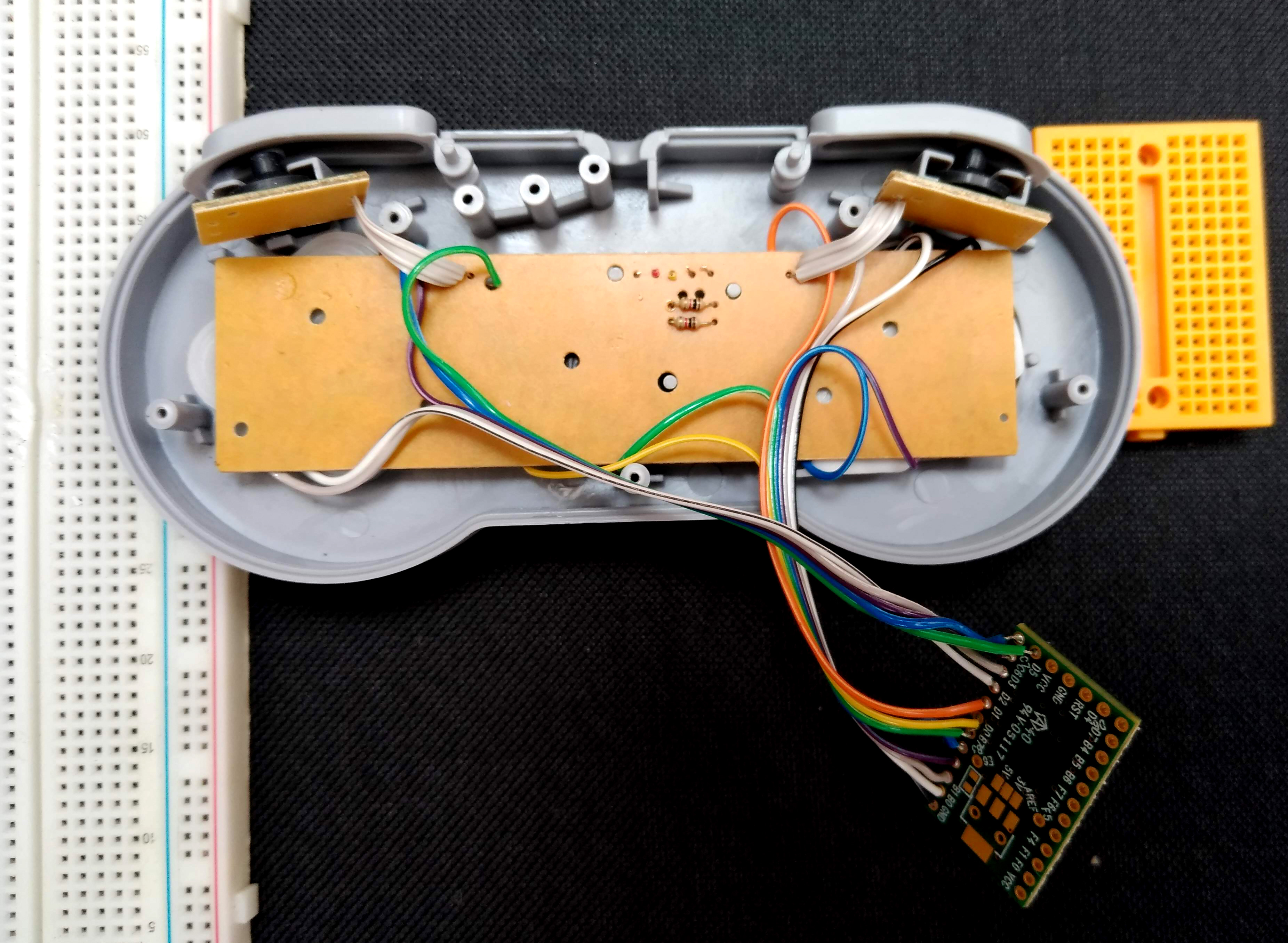
- Find a space for the Teensy and cable. This is the hardest part. You can use some double-sided tape to secure it in place. You might find that separating the cables in the ribbon aids the process. Be mindful of the position of the screw holes, ensure that no cables obstruct them.
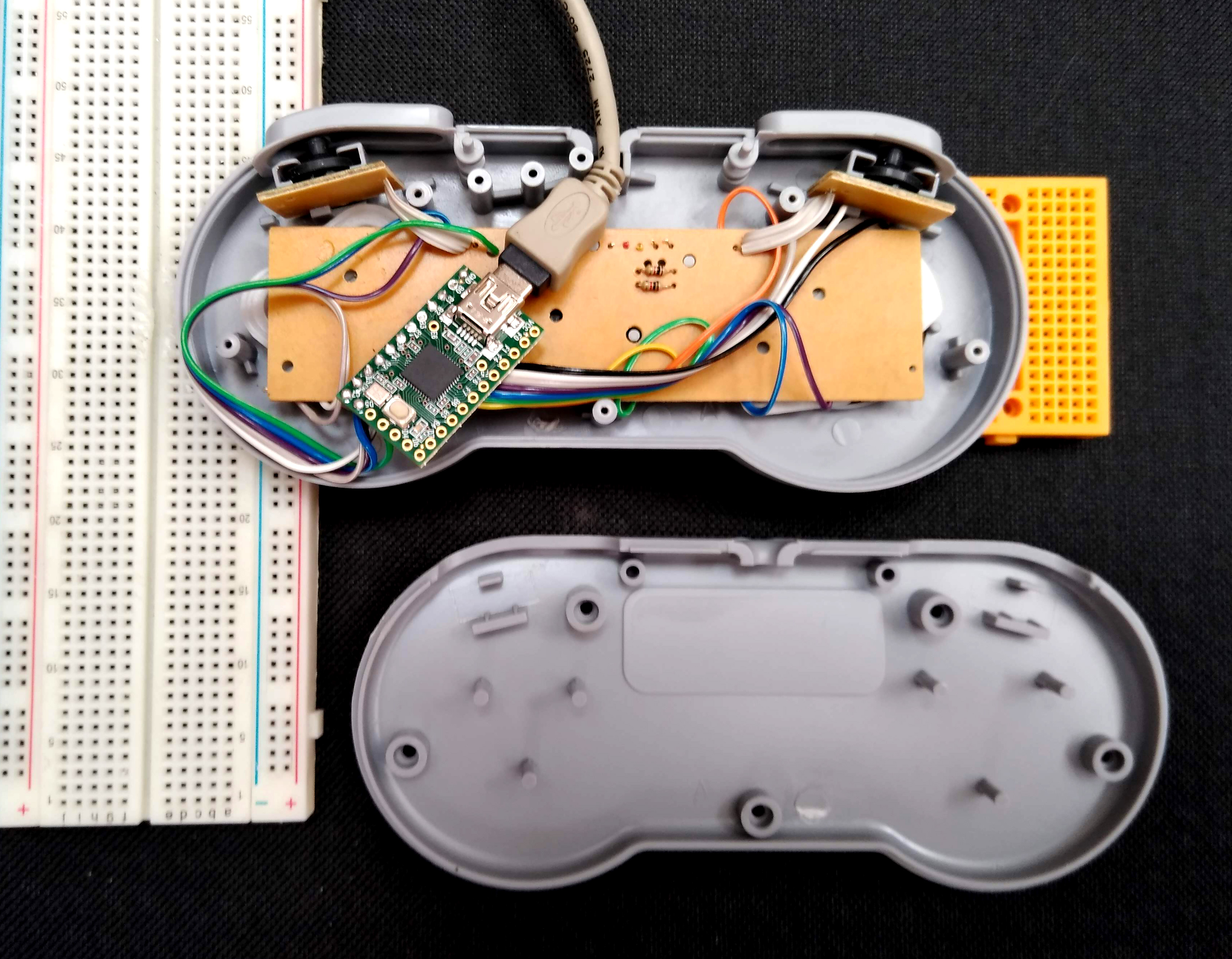
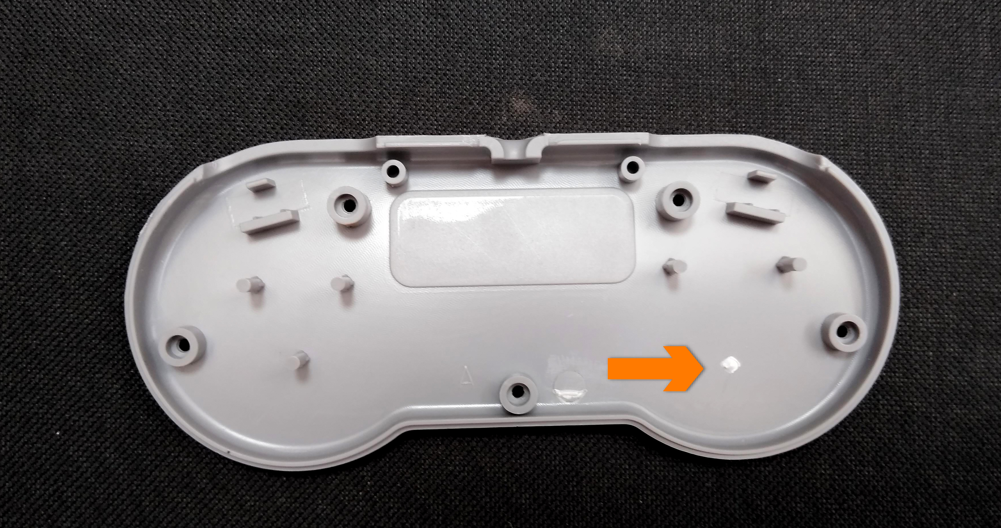
- Make sure that the standoffs on the controller’s back don’t get in the way. You might have to snap some off. In our case, the one marked below had to go.
- Carefully place the back on ensuring that it all fits as it should. At this stage, it is a good idea to secure just a couple of screws and then test the controller to ensure that all the buttons are working and no connections have been damaged.
- Once you’re happy that everything works you can secure the remaining screws.
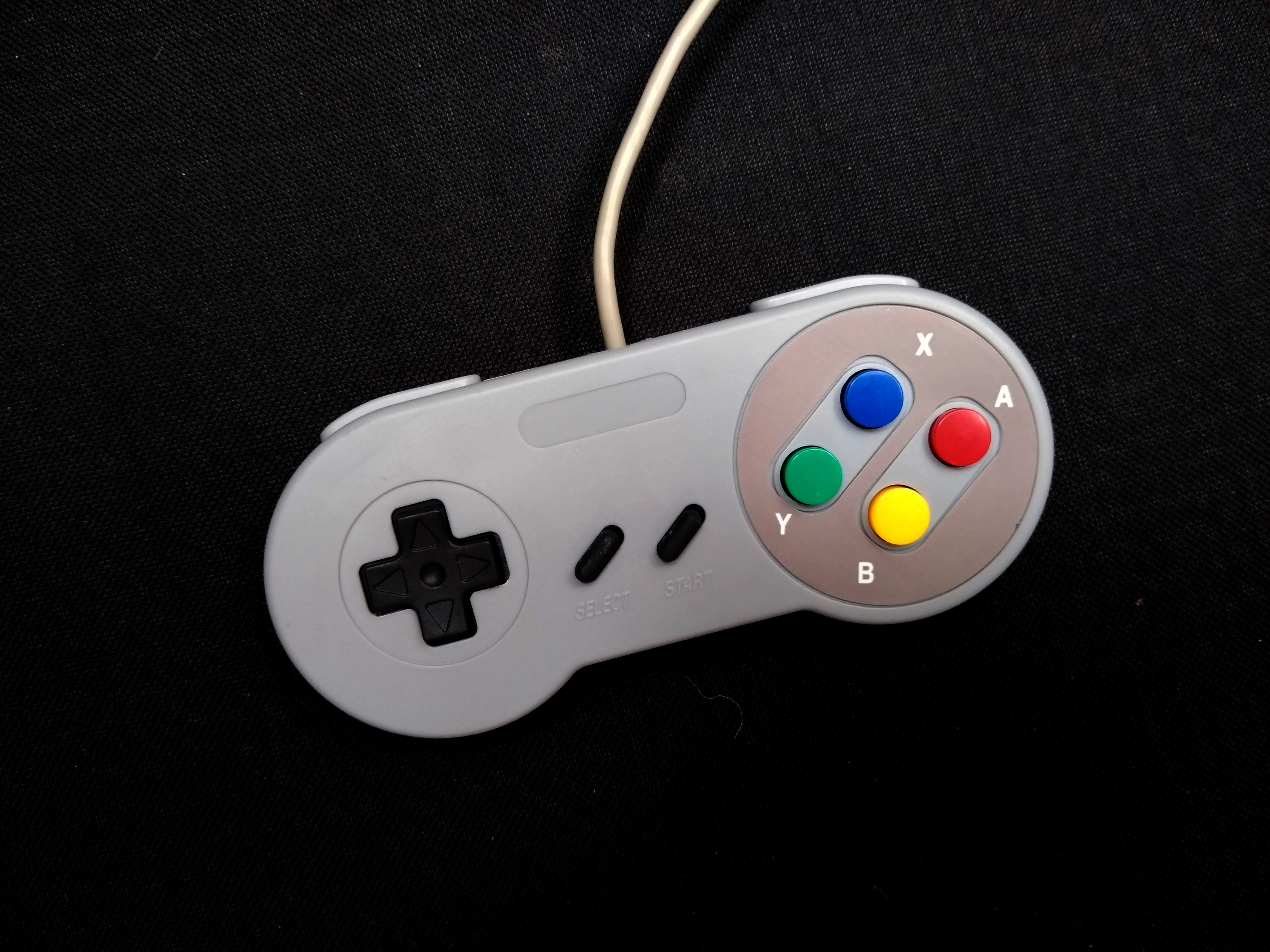
You’re ready to play!
Like what you read? Why not show your appreciation by giving some love.
From a quick tap to smashing that love button and show how much you enjoyed this project.

