Connecting an LED to a GPIO pin can be done and is frequently done. But this will only work if the LED has a forward voltage drop of less than 5V (or 3.3V with some GPIO (some even as low as 1.1V!)). GPIO are often limited to around 20mA and taking the Arduino Mega for example, some GPIO rails can deliver 100mA max, so that would only be 5 LEDs on at a time. Not only that but if each LED takes up a single GPIO, you’re limited by the number of GPIO you have, and often not many pins have PWM ability, so you can’t even dim them.
This project will look at different ways of driving LEDs, their relative merits and also design considerations.
Driving standard 20mA LEDs
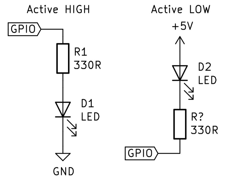
The standard method for driving a low power LED (often used just for debugging) can be wired directly to a GPIO as shown below
These LEDs are very cheap and for the most part aren’t that bright. They aren’t designed to do much more than be on or off just to indicate something, like power or an activity indicator.
To choose the right resistor (R1 and R? in the schematic) you will need to know:
- The voltage of the GPIO pins (normally 5V for Arduino and 3.3V for Raspberry Pi)
- The forward voltage drop of the LED (1.8V – 3.3V for low powered ones)
- The current of the LED (around 20mA for a low power one)
You can then use V=IR to find the value of R1 which works out to be:
R1 = (GPIO voltage – forward voltage drop) / (LED current)
A safe bet is normally 330 -> 500 ohms.
You will also need to calculate the power dissipated using P=IV=RI^2 so the resistor doesn’t overheat. At 20mA and 500 ohm resistor, you would need a 200mW resistor, but the standard through hole resistor is 0.25-0.5W so this is fine unless you have multiple LEDs
Driving a high power LED
High power LEDs can range from 3W all the way up to 500W (above 10W is very bright and should be used with care to prevent damage to your eyes). High power LEDs also often use voltages much higher than the 5V an Arduino uses at much higher currents. Many 10W LEDs run at 12V and nearly all 100W LEDs run at 30V or more using several amps, so running it off the GPIO won’t do very much.
A solution to this is a logic level MOSFET. You can use BJTs, but MOSFETs are better in my opinion so that is what this tutorial will use. You will also need an external power supply for the LED and possibly a resistor as described in step 1, but this depends on the driver you have (we will touch on this later).
MOSFETs come in two flavours, N-MOS and P-MOS. Due to how they are made, N-MOS have a lower on-state resistance and thus have lower on-state losses, they are also really easy to drive with an Arduino if you choose a logic level device, so we will only consider N-MOS, but feel free to read up on driving P-MOS and other high side driven devices.
The basic schematic for the circuit is below with R2 acting as an option pull down resistor so the LED won’t shine if the GPIO was to go high impedance input:
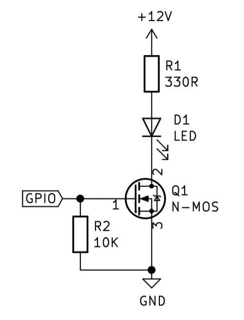
As you can see it is really rather simple, the difficulty in this design is learning what MOSFET to choose. There are thousands and thousands of MOSFETs to choose from, but as what we are doing is very simple and not high frequency stuff, you can narrow it down by searching MOSFET on RS and refining the results as follows
- Choose a through hole device
- Select N type
- Find a low on-state resistance (less than 0.1 ohm or much lower if high power (50W or higher))
- Check the MOSFET drain-source voltage is rated to 1.5x the voltage of the LED you’re driving
- Check the MOSFET is rated to the current you plan on needing
- Check that the maximum gate threshold voltage is below around 2.5V
After all this, use the current of the LED, the on-state resistance of the MOSFET and P=RI^2 and make sure the MOSFET can dissipate the heat it will produce. If not, you might need a heatsink on the MOSFET.
Choosing the correct power supply
LEDs are a current controlled device, not voltage as some people think. When selecting a power supply for the LED you have a few options. With low power things you will be just fine if you use the standard 5V/3.3V rails on a device with a current limiting resistor as shown in step 1. The power supply for this is constant voltage, meaning it trys to maintain the voltage at a constant level and the current changes. With a high power LED, using this method can become very inefficienct and the brightness of the LED will change as things heat up as the value of the resistor will change as it gets hotter.
A solution to this is a constant current constant voltage regulator (they are easy to find and are often just called LED drivers). These devices can often step an input voltage up or down to whatever the LED needs, but most importantly they will lower their output in order to not go above a current limit you specify. This means when you switch it on the driver will regulate the LED at constant voltage and then when it heats up and draws more and more current, once it reaches a threshold (lets say 2A) it will lower the voltage in order to maintain a maximum of 2A which is much better for the health of the LED.
Not enough GPIO - matrix solution
What do you do if you don’t have enough GPIOs? The Arduino Uno allows for up to 20 GPIO pins, so you could have 20 LEDs if you used the previous concepts, but then you have no room for anything else, and what if you wanted even more than 20 LEDs?
Well one solution is to wire the LEDs in a matrix layout as shown below:
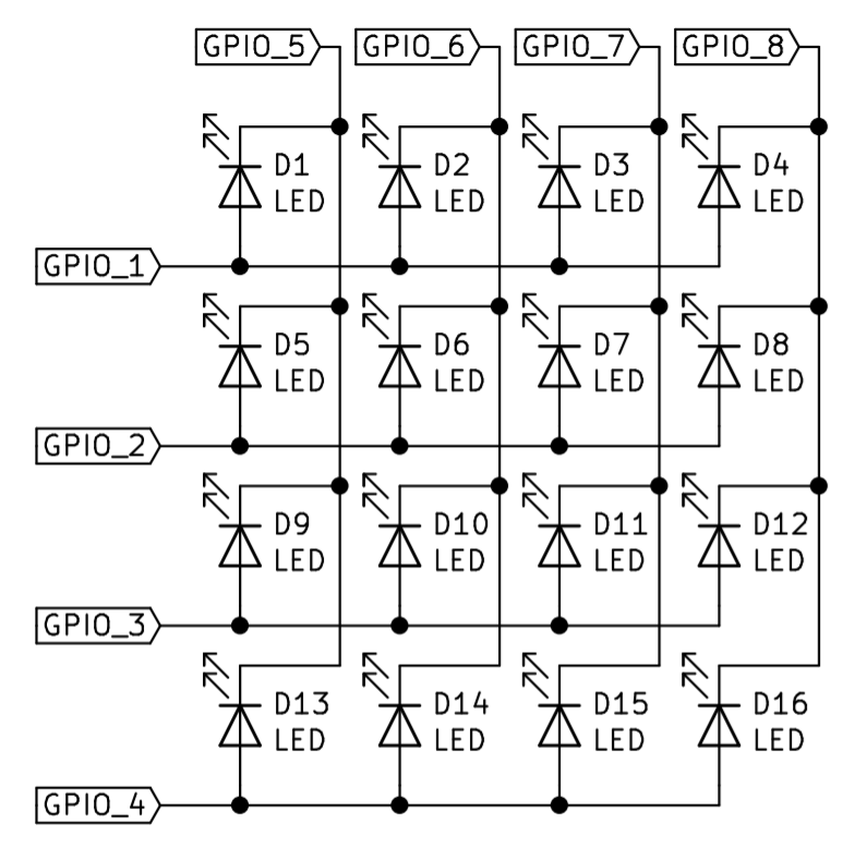
This only uses 8 GPIO, but allows you to drive 16 LEDs, but scales up, i.e using 16 gpio gives rise to 64 LEDs you can drive. The only downside is that you have to drive it column by column (or row by row) such that you can only really control 4 LEDs at a time, but if you flick between them fast enough, you can’t see it by the human eye.
The way it works is, for example, if you wanted the LED on the fourth column along and third row down (D12) to be on, you would pull GPIO 8 low and GPIO 3 high, which in turn would only turn the LED in the fourth column along and third row down on. You would however need to pull GPIO 1, 2 and 4 low and GPIO 5, 6 and 7 high in order to only turn the D12 LED on.
This method is useful for a quick and cheap way to turn the LEDs on, but without an external driver (which will be mentioned next) you might have a noticeable amount of flickering and often results in more complexity.
Not enough GPIO- external drivers
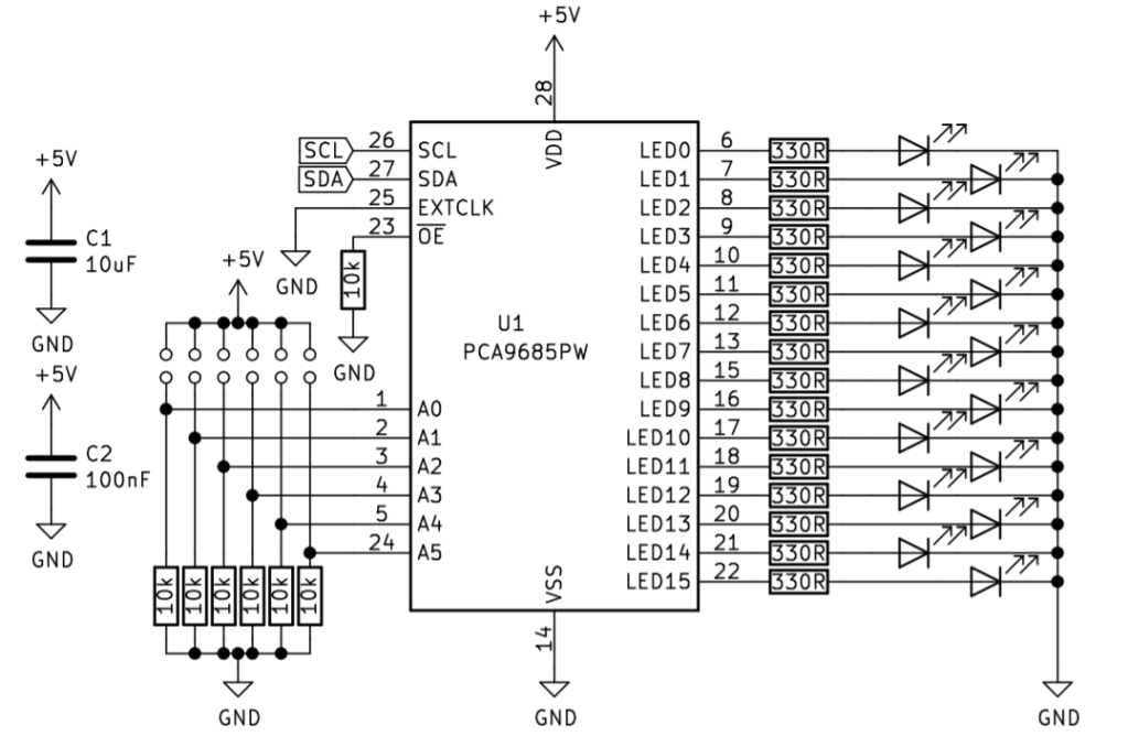
Another way of driving lots of LEDs is to use something like the PCA9685 IC which uses I2C in order to give you up to 16 extra PWM outputs. You can also have multiple of these on the I2C if you need more, but this may limit data rates. These PCA9685 modules are often sold as servo drivers, but they work on a duty from 0-1 so you can easily use them as LED drivers.
The PCA9685 does however have a 25mA limit, which means you are stuck with lower powered LEDs, although you can still connect the output to a MOSFET and drive higher powered LEDs, but it is quite rare for you to need to drive so many high powered LEDs.
The schematic for the PCA9685 is shown below, with their being option jumpers on A0-A5 for selecting the I2C address. C1 acts as a charge pool so the LEDs can find the current to switch on rapidly and C2 acts as a decoupling capacitor to lower noise and should be put as close as possible to the IC.
There are many LED drivers out there and many of which use different types of interfaces like serial or SPI, but have a look around and see what you can find. Any driver which uses an interface as apposed to just being a driver means that you can save many GPIO and also results in lower complexity as you don’t need to worry about programming the stepping through rows and columns like what would bee needed in step 4.
Not enough GPIO - addressable LEDs
Sometimes you need to drive a whole bunch of LEDs, so you can use addressable LEDs like that of the WS2812 (a commonly used Addressable LED).
These often come in strips or panels, but can be found as individual LEDs on a board for example this
These work by providing the LEDs with 5V (sometimes 12V) and GND and then a data pin. The data pin is a single wire which is connected to a GPIO pin on the Arduino. The data is bit banged into the data input of the LED and then the data is output again to the next LED via the output pin on the LED. The data is sent in such a way that each LED will receive the data for its colour and brightness in order so that you are able to specify things like the 3rd LED in the string is green and the 4th is orange. These LEDs can be changed at 800Hz (limited by how many you put in a chain) and mean that you only need one pin on the Arduino.
All of this can be handled by libraries like that of the Adafruit_NeoPixel library which means you only have to provide the colour and brightness and it will handle the rest. These kind of LED were used on our arcade project found here.
Choosing the right LEDs
We hope this list of options gives you some insight into how to better drive LEDs. This isn’t the entire list of options but gives you an idea of some of the simplest options. You might need to do some more reading into how to better implement your idea into a specific application but you should have a good grounding as to what you might need. A lot of choosing the right kind of method of driving comes down to experience, but if you want my advice:
- If you want it quick and pretty, use addressable LEDs
- If you need it bright as possible (like a torch) use a MOSFET to drive a big LED
- If you need lots and lots of LEDs but you want to use your own choice of LEDs use external drivers like the PCA9685, and if needed have each output of the IC drive a MOSFET which drives an LED
- If you just need a simple LED to blink to tell you it hasn’t crashed, just wire it directly to the GPIO with a resistor
Like what you read? Why not show your appreciation by giving some love.
From a quick tap to smashing that love button and show how much you enjoyed this project.

