
This getting started demonstrates setting up the DEBIX Model A with the I/O development board and includes installing Debix OS (Ubuntu), building new kernels, cross-compiling applications and testing systems communication using CAN bus.
Author: Peter Milne, engineer and Linux advocate with more SBCs than an Apollo 11 landing craft.
DEBIX Model A is an industrial grade single board computer featuring an i.MX 8M Plus processor with 4 Arm® Cortex®-A53 cores running at 1.6GHz, a 2.3 TOPS Neural Processing Unit (NPU) and 2GB LPDDR4 RAM.
The board features a wide range of interfaces including; 4 x USB 3.0 type A connectors, 1 USB-C OTG connector, Gigabit Ethernet with POE support, 2.4G & 5G dual-frequency WIFI, BT5.0, HDMI, Audio In/Out, MIPI CSI & DSI display connectors, 40 pin GPIO header including 2 x CAN and PCIE and LVDS connectors.
With a familiar 86mm x 56mm form factor, it can operate over a wide temperature range from -40℃ to 105℃, performing advanced processing tasks in extreme environments.
Power input is 5V / 3A via USB-C with reset and On/Off buttons.
Software support is excellent with high quality 64-bit images for Ubuntu 20.04, Yocto-L5.10.72_2.2.0, Win10 IoT Enterprise and Android 11.
A standout feature of this SBC is the online hardware and software documentation and the availability of the DEBIX Model A add-on I/O board.
Let’s get started!
| Difficulty: Medium | Time: 3 Hrs | Steps: 13 | Credits: None | License: None |
Parts Needed to Get Started with the DEBIX Model A and IO Add-on board
DEBIX Model A Single Board Computer
DEBIX Model A I/O Board
All parts needed to get started:
- DEBIX Model A Single Board Computer
- DEBIX Model A I/O Board
- 5V / 3A Power Supply
- Micro SD Card
- USB C Cable
- Arduino Portenta Machine Control
- Host PC
- Ethernet Cable
- Internet Connection / Router
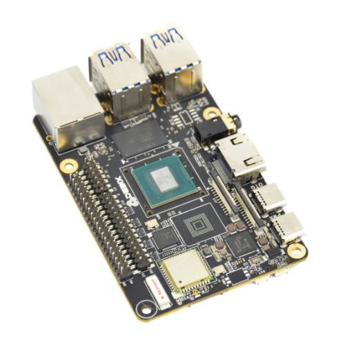
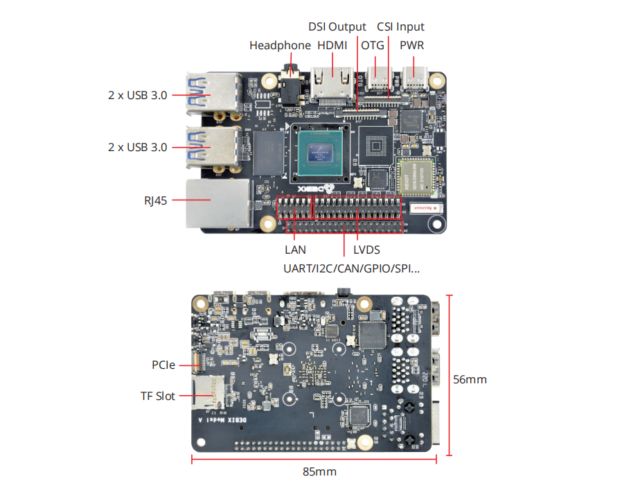
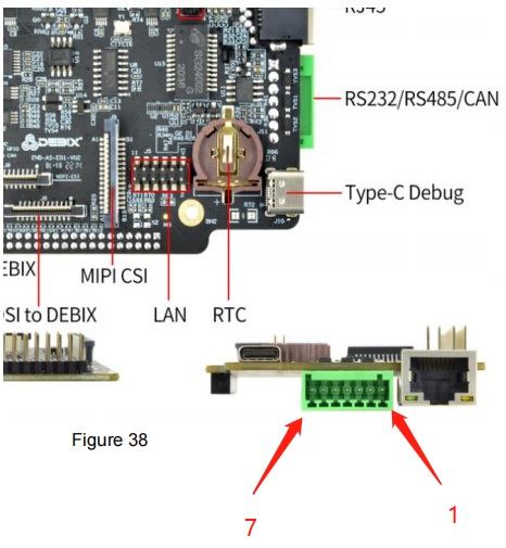
Step 1: DEBIX Model A Connectors
The image below shows the connectors on the top and bottom of the main board, including the 40 pin GPIO header that the I/O board connects to.
Detailed information about the board including schematics can be found on the DEBIX website.
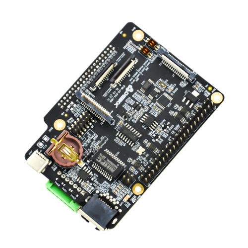
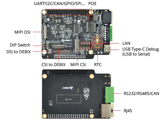
Step 2: DEBIX I/O Board
The I/O add-on board simplifies development and adds several useful features:
- USB-C to Serial port for debugging
- Adds one RJ45 Gigabit network interface and PoE function
- Allows connection with industrial peripherals through RS232, RS485 and CAN transceiver
- MIPI CSI, MIPI DSI and GPIO pin headers
- RTC and backup battery holder
Detailed documentation including schematics can be found on the DEBIX website.
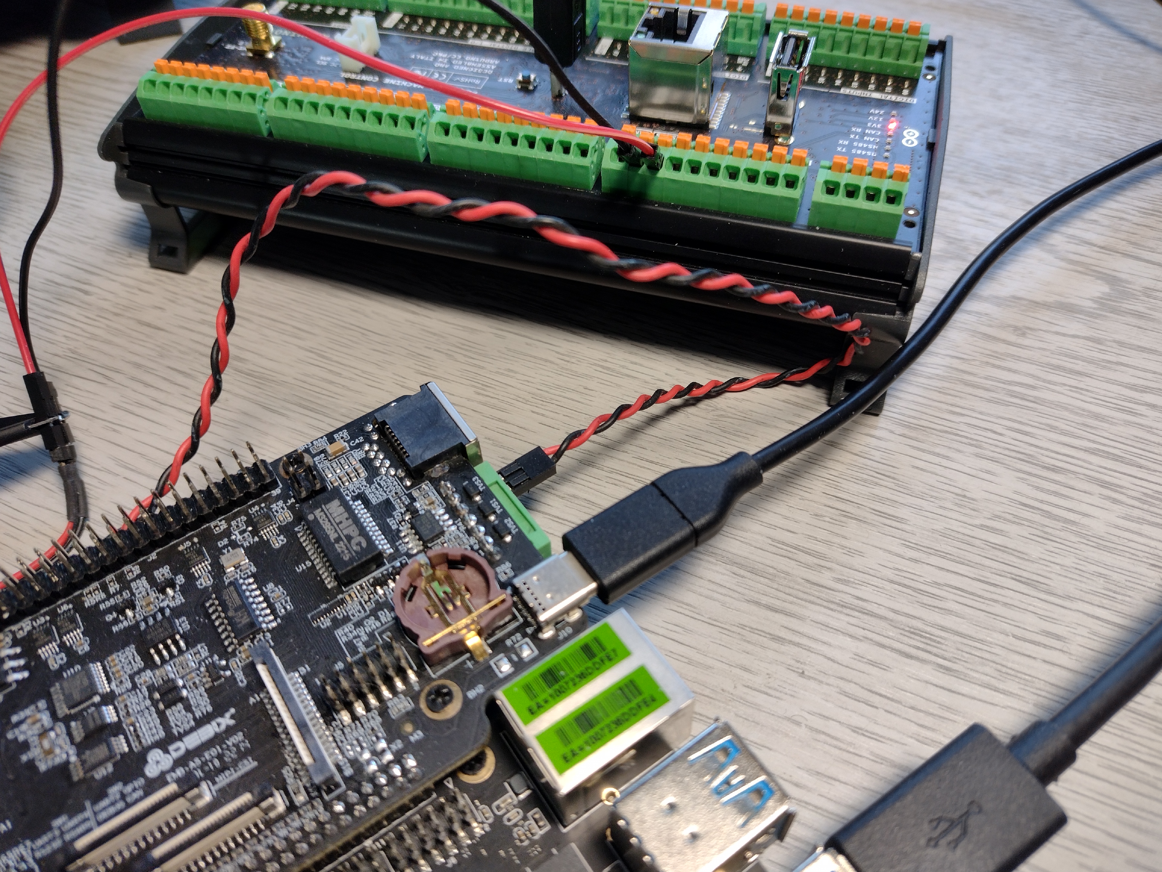
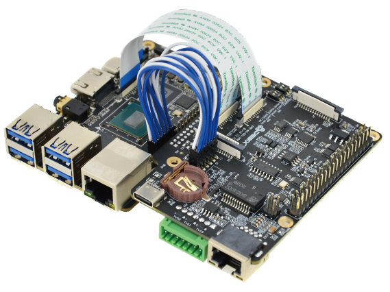
Step 3: Hardware Setup
Prepare the two boards by connecting them together using the 40 pin header on the Model A board and add the ribbon cable and jumper wire connectors as shown below. All connector cabling is supplied with the Add-on board.
In addition, connect the I/O board to a host PC using the USB-C connector next to the RTC battery holder to provide access to the serial console.
Connect a 5V / 3A fixed power supply to the USB-C connector on the main board marked PWR (nearest to the corner of the Model A board) – do not power on yet.
Tip: the ribbon cables and wire jumper cable is only required for the display and Ethernet capability
Step 4: DEBIX OS
Debix provides several official OS images for the Model A including a desktop version of Ubuntu 20.04 (Debix OS), Android 11, Yocto-L5.10.72_2.2.0 and Win 10 Enterprise. The images are all available from the Debix Software page and are updated regularly
We tested the Debix OS image flashed to a good quality SanDisk Ultra 32GB SD card.
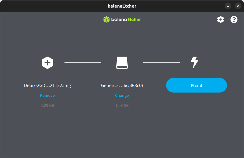
- Visit the DEBIX software page and download Ubuntu 20.04 for the Model A & B 2G DDR Version (4GB file size)
- Insert the SD into the PC card reader
- Open BalenaEtcher and select the downloaded image from your download directory
- Select the SD card
- Flash the image to the card. This takes a while so take a coffee break!
When the image has flashed successfully remove the SD card from the PC and insert it into the microSD card slot on the Model A board
Step 5: First Boot
We attached the I/O board to a Linux PC running Ubuntu Jammy and used minicom to display the serial console. You can use similar applications if you use Windows or Mac.
Minicom is available from the repos on most Linux distros:
sudo apt install minicomOpen a terminal and start minicom on ttyUSB0 at 115200 baud:
minicom -b 115200 -D /dev/ttyUSB0- Power on the board and the red LED next to the USB-C PWR connector will turn on.
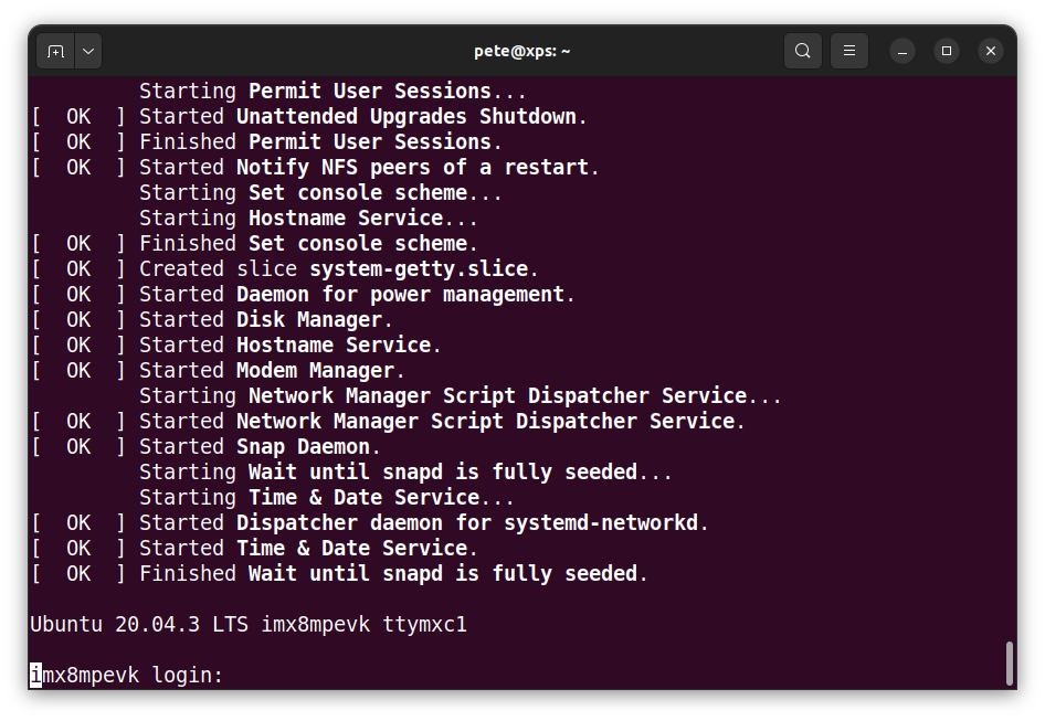
- You will see the boot messages scrolling in the console – wait for the bootup sequence to complete which can take just over a minute on the first boot so be patient.
- When everything is ready you will see the login prompt – login with the following credentials:
Default user: debex
Default password: debex
Step 6: SSH Access
SSH access is enabled by default so if you have attached an Ethernet cable to the board then you can login remotely.
Open another terminal and ping the hostname which is imx8mpevk
ping imx8mpevk
Run ssh on your host and login with the default credentials above:
ssh debix@imx8mpevk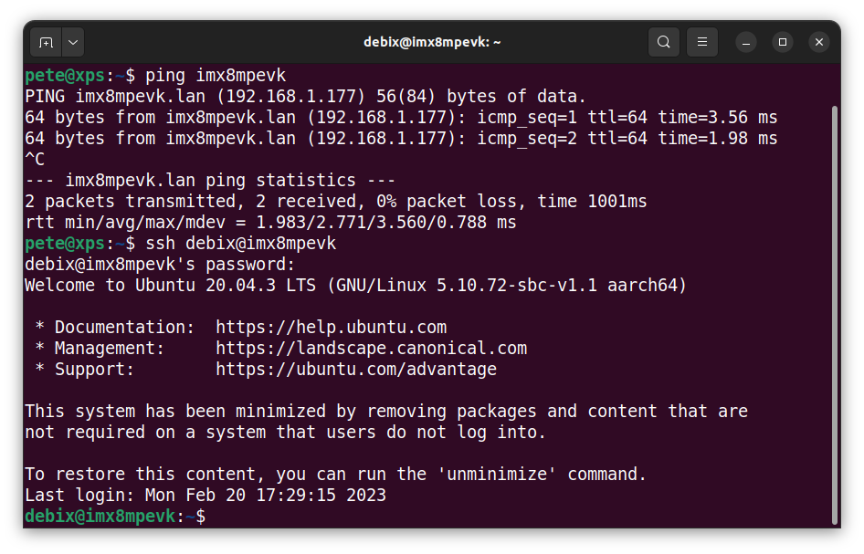
Step 7: Safe Shutdown
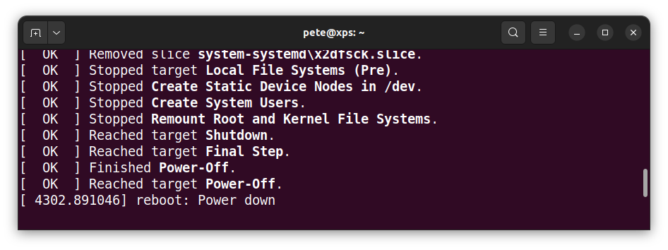
To preserve the SD card make sure to shutdown correctly before powering off the board:
- From the system prompt in the console, enter the poweroff command:
sudo poweroffThis will close all the operating system processes and start the shutdown routine. When it has completed you can turn off the power to the board.
Tip: You can leave the power connected and press the Power On / Off button to restart the system
Step 8: Kernel Build
Cross-compiling a new kernel on a Linux host is straight forward. These commands were tested on a Linux PC running Ubuntu 22.04 (Jammy) using a pre-flashed SD card with a previous version of Debix OS installed, so that just the kernel modules and device tree needed to be updated.
- Debix use the Keil ARM compiler which is free to download:
sudo mkdir /opt/toolchain

cd /opt/toolchain

sudo wget
https://armkeil.blob.core.windows.net/developer/Files/downloads/gnu-a/9.2-2019.12/binrel/gcc-arm-9.2-2019.12-x86_64-aarch64-none-linux-gnu.tar.xz

sudo tar xpf gcc-arm-9.2-2019.12-x86_64-aarch64-none-linux-gnu.tar.xz- Install the build dependencies:
sudo apt install git bc bison flex libssl-dev make libc6-dev libncurses5-dev- Change to your home directory and clone the Debix kernel sources, then rename the kernel tree:
cd

git clone --depth=1 https://github.com/debix-tech/linux

mv linux debix-kernel- Export the path to the cross-compiler (all on one line):
export PATH=$PATH:/opt/toolchain/gcc-arm-9.2-2019.12-x86_64-aarch64-none-linux-gnu/bin- Change into the root of the kernel tree and clean the source tree:
cd debix-kernel

make ARCH=arm64 CROSS_COMPILE=aarch64-none-linux-gnu- mrproper- Configure the build system then add a local version string using menuconfig:
make ARCH=arm64 imx_v8_defconfig

make ARCH=arm64 menuconfig
Set CONFIG_LOCALVERSION eg “-test-v1.0”
- Build the kernel, modules and Devicetree binaries – this can take a while depending on how fast your host is!
make -j $(nproc) ARCH=arm64 CROSS_COMPILE=aarch64-none-linux-gnu-Tip: If prompted for new config options accept the default by pressing enter
Step 9: Kernel Update
- Insert an SD card flashed with a previous version of DEBIX OS into the host card reader.
- Create mount points on the host for the SD card partitions:
sudo mkdir -p /mnt/fat32

sudo mkdir -p /mnt/ext4
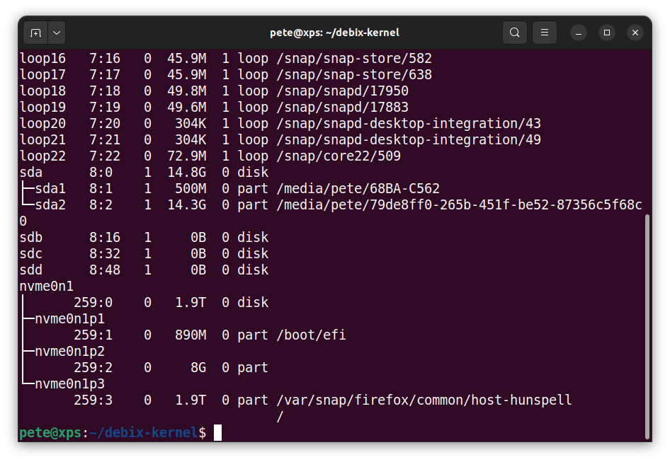
List the block devices and make sure to know which disk and partitions represent your SD card.
In this example sda1 is the 500MB FAT partition which holds the boot files and sda2 is the 14.3GB EXT4 partition which holds the root file system on the 14.8GB SD card.
Your SD card may be mounted differently on your system, so you will need to change the /dev/<partition> commands below to match your settings.
Warning: If you write to your host partitions you can prevent your host from booting!
- Mount the SD card partitions on the host according to the drive names on your system:
sudo mount /dev/sda1 /mnt/fat32

sudo mount /dev/sda2 /mnt/ext4
- Install the modules to SD card then unmount the root file system:
sudo env PATH=$PATH make ARCH=arm64 \

CROSS_COMPILE=aarch64-none-linux-gnu-INSTALL_MOD_PATH=/mnt/ext4 \

INSTALL_MOD_STRIP=1 modules_install

sudo umount /mnt/ext4
- Copy the kernel and device tree binaries to the SD card, then unmount the boot partition:
sudo cp /mnt/fat32/Image /mnt/fat32/Image-backup.img

sudo cp arch/arm64/boot/Image /mnt/fat32/Image

sudo cp arch/arm64/boot/dts/freescale/*.dtb /mnt/fat32/

sudo umount /mnt/fat32
Now remove the SD card and put it back in the Debix board. Use the debug USB-C port on the I/O board and open a serial terminal on the host.
- Power the board on and watch it boot.
You should now have a new kernel which you can check with uname:
uname -rStep 10: C Programming
This section shows how to use the cross-compiler we installed earlier to compile your own C code to run on the Model A.
- Open a terminal on your host and export the path to the compiler:
export PATH=$PATH:/opt/toolchain/gcc-arm-9.2-2019.12-x86_64-aarch64-none-linux-gnu/binUsing your favourite editor create this example code and save it as test.c:
#include <stdio.h>

#include <stdint.h>


int main(int argc, char **argv) {

  printf("Size of char: %zu\n", sizeof (char));

  printf("Size of int: %zu\n", sizeof (int));

  printf("Size of long int: %zu\n", sizeof (long int));

  return 0;

}
- Build the ArmV8a 64-bit application with dynamic linking on the host:
aarch64-none-linux-gnu-gcc test.c -o test-armv8a- Check the executable type:
file test-armv8a

test-armv8a: ELF 64-bit LSB executable, ARM aarch64, version 1 (SYSV), dynamically linked, interpreter /lib/ld-linux-aarch64.so.1, for GNU/Linux 3.7.0, with debug_info, not stripped
- Copy the executable from the host to the Model A board in the debix user home directory:
scp test-armv8a debix@imx8mpevk:~/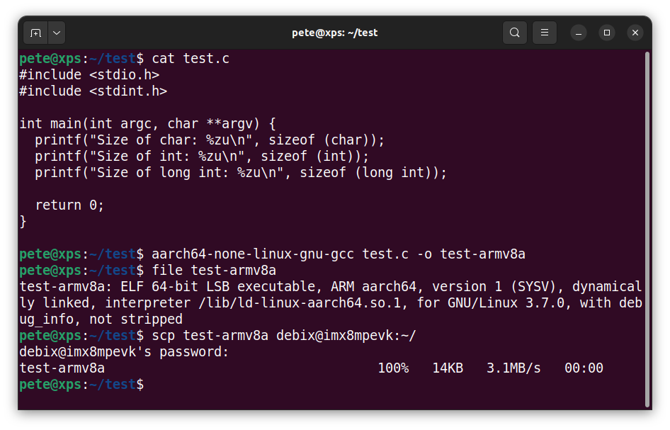
- Login to the Debix target and run the executable:
./test-armv8a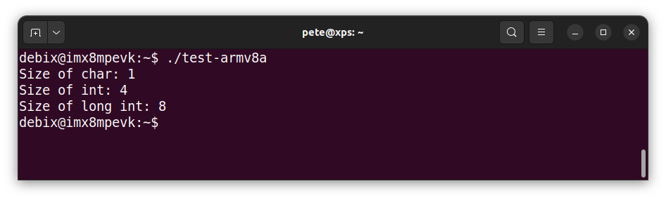
Step 11: CAN Bus
The Model A board has 2 CAN ports; CAN1 & CAN2 which are available on the GPIO header of the I/O board. These need connecting to a compatible 3.3V CAN transceiver before they can be attached to the CAN bus. This is the default setting when switch SW2-2 is ON.
The I/O board has a single built in NXP TJA1040T CAN transceiver that can be used with CAN1 by setting SW2-2 OFF. This routes CAN1 via the transceiver to connector J12 which provides CAN_H & CAN_L signals via the green 7pin KEEFA KF2EDGKD-2.5 connector.
TJA1040T CAN transceiver is compatible with ISO 11898 standard for handling high speed data rates up to 1 MBaud.
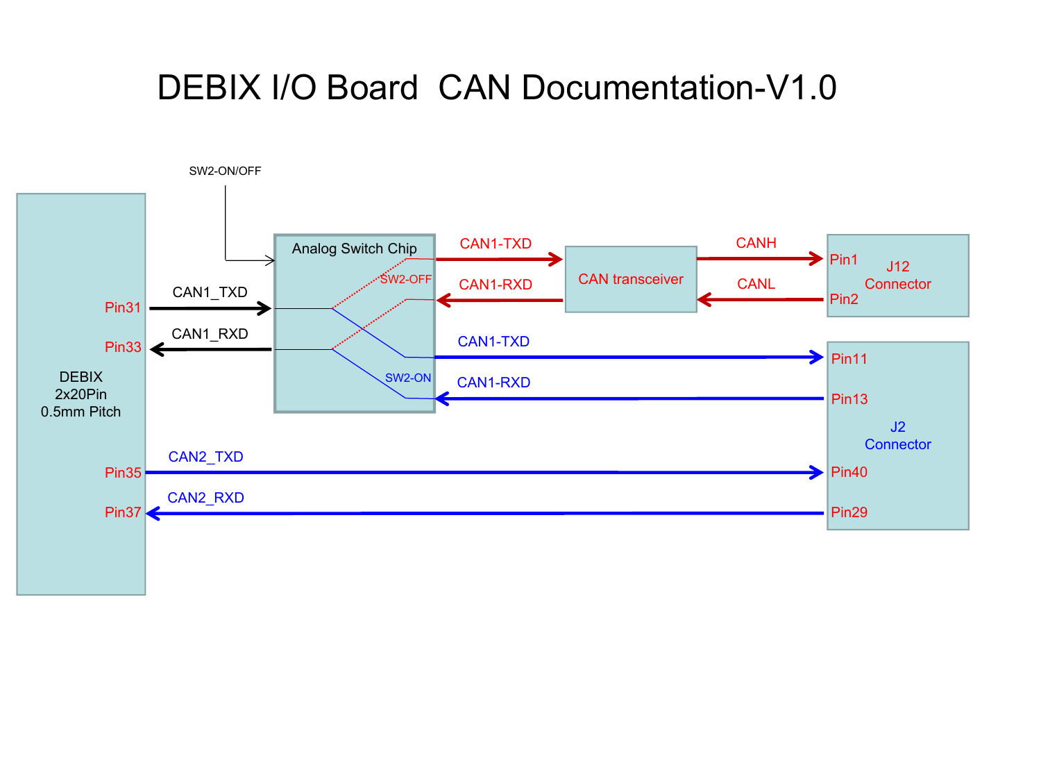
Setting SW2-OFF routes CAN1_TX and CAN_1RX via the CAN transceiver to connector J12
J12 Pinout:
| Pin | Signal | Switch |
|---|---|---|
| 1 | CAN_H | SW2-2 OFF |
| 2 | CAN_L | SW2-2 OFF |
| 3 | RS485_AH | SW1-2 OFF |
| 4 | RS485_BL | SW1-2 OFF |
| 5 | RS232_RXD3 | SW1-1 OFF |
| 6 | RS232_TXD3 | SW1-1 OFF |
| 7 | GND |
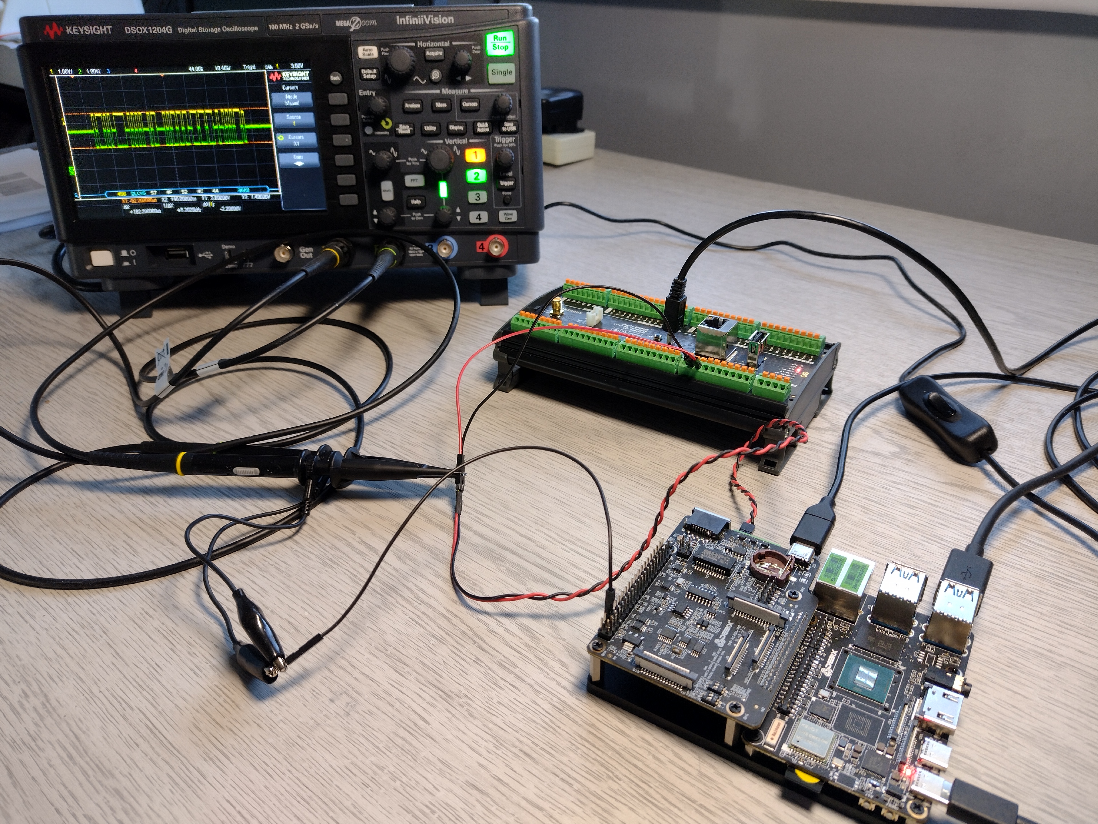
To test the CAN bus we connected the Debix board to a Portenta Machine Control (PMC) board which has a built-in transceiver. Alternatively you could use an Arduino MKR with CAN shield.
- Using a twisted pair cable, connect CAN_H / CAN_L on the Model A J12 connector to CAN_H / CAN_L on the PMC connector J5. We also attached an oscilloscope to the CAN bus to capture the signals.
| DEBIX Model A I/O J12 | PMC J5 | Signal |
|---|---|---|
| Pin 1 | Pin 8 | CAN_H |
| Pin 2 | Pin 9 | CAN_L |
Note: PMC board documentation describes CAN connections as CAN_TX / CAN_RX but they are CAN_H & CAN_L
Step 12: CAN Send
A Bash script was used to send messages from the Debix board to the CAN bus. The CAN1 interface is appears as the device /dev/can0 and the cansend utility can be used to send CAN frames with the following signature:
cansend <can_interface> <can_id#candata[0..8 bytes]>Create the following Bash script can-send.sh which runs on the Model A board – it continuously sends 2 messages one second apart:
#!/bin/bash

# Send CAN 2.0 data frames continuously

while :

do
	#can_id 123, data HELLO

	cansend can0 123#48454C4C4F;

	sleep 1;

	#can_id 456, data WORLD

	cansend can0 456#574F524C44;

	sleep 1;

done
- Login to the Model A board and copy the script to a file.
- Configure the CAN bus and bring up the interface:
sudo ip link set can0 type can bitrate 1000000

sudo ifconfig can0 up
- Check the interface is up with ifconfig:
ifconfig

can0: flags=193<UP,RUNNING,NOARP>  mtu 16

        unspec 00-00-00-00-00-00-00-00-00-00-00-00-00-00-00-00  txqueuelen 10  (UNSPEC)

… - Now run can-send.sh to start sending messages, use CTRL + C to quit:
sudo ./can-send.shStep 13: CAN Receive
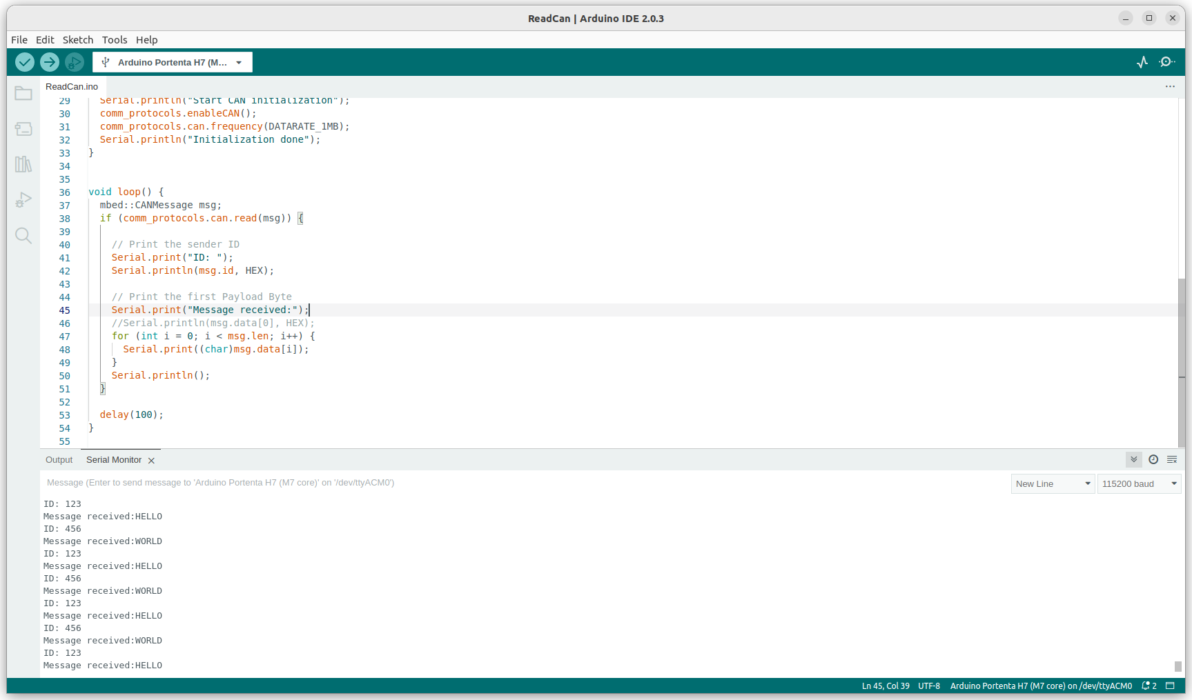
To view the messages on the PMC we used the Arduino IDE to flash a slightly modified version of the ReadCan example code. This sets the bus speed to 1M Baud, listens for any CAN frames and prints the CAN id and data from the received message:
#include <Arduino_MachineControl.h>

#include <CAN.h>

using namespace machinecontrol;

#define DATARATE_1MB 1000000

void setup() {
  Serial.begin(115200);
  while (!Serial) {
    ;
  }
  comm_protocols.enableCAN();
  comm_protocols.can.frequency(DATARATE_1MB);
  Serial.println("CAN initialized");
}

void loop() {
  mbed::CANMessage msg;
  if (comm_protocols.can.read(msg)) {
    Serial.print("ID: ");
    Serial.println(msg.id, HEX);

    Serial.print("Message received:");
    for (int i = 0; i < msg.len; i++) {
      Serial.print((char)msg.data[i]);
    }
    Serial.println();
  }
  delay(100);
}
- Connect the PMC to the host using the micro USB connector on the PMC, flash the code to the H7 core and open the Serial Console which waits for any messages to be received.
You should see the message CAN id and data being received in the serial console.
Summary
The Debix Model A board is a high quality SBC suitable for industrial applications. The addition of the I/O add-on board makes it a useful development platform along with excellent software and documentation support.
In this getting started we showed how to setup the main board with the I/O add-on and boot and test the Debix OS which is a spin of Ubuntu 20.04.
We demonstrated building and installing the latest kernel from the Debix BSP and cross-compiling C code along with investigating communication with another industrial controller board via CAN bus.
The example code is available in the OKdo GitHub repo.
Documentation is available on the DEBIX website.
You can download the OS from the DEBIX website.


LET’S INVENT THE FUTURE TOGETHER
What’s your challenge? From augmented reality to machine learning and automation, send us your questions, problems or ideas… we have the solution to help you design the world.